DeviceNet™ Communications Module Catalog Number 1203-GK5 or 1336-GM5 Firmware 1.xxx-3.
Important User Information Solid state equipment has operational characteristics differing from those of electromechanical equipment. “Safety Guidelines for the Application, Installation and Maintenance of Solid State Controls” (Publication SGI-1.1 available from your local Allen-Bradley Sales Office or online at http:// www.ab.com/manuals/gi) describes some important differences between solid state equipment and hard-wired electromechanical devices.
Summary of Changes Summary of Changes The information below summarizes the changes made to the manual since the last release. These changes are a result of the 3.xxx firmware upgrade. DeviceNet Communications Modules with firmware 3.xxx support an internal (Rockwell use only) Object for use with IntelliCENTER™ software. This firmware update is transparent to the user.
soc–2 Notes Summary of Changes
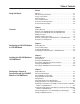
Table of Contents Preface Using this Manual Objectives . . . . . . . . . . . . . . . . . . . . . . . . . . . . . . . . . . . . . . . . . . . . . . . . . P-1 Who Should Use this Manual? . . . . . . . . . . . . . . . . . . . . . . . . . . . . . . . . . P-1 Purpose of this Manual . . . . . . . . . . . . . . . . . . . . . . . . . . . . . . . . . . . . . . . P-1 Safety Precautions. . . . . . . . . . . . . . . . . . . . . . . . . . . . . . . . . . . . . . . . . . . P-3 Terms and Abbreviations . . . . . . . . .
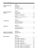
toc–ii Table of Contents Chapter 5 Creating a Ladder Logic Program Chapter Objectives. . . . . . . . . . . . . . . . . . . . . . . . . . . . . . . . . . . . . . . . . . . 5-1 Required Equipment . . . . . . . . . . . . . . . . . . . . . . . . . . . . . . . . . . . . . . . . . 5-1 About RSLogix . . . . . . . . . . . . . . . . . . . . . . . . . . . . . . . . . . . . . . . . . . . . . . 5-1 About Ladder Logic Programs . . . . . . . . . . . . . . . . . . . . . . . . . . . . . . . . . .
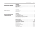
Table of Contents toc–iii Appendix D Supported PCCC Messages Appendix Objectives . . . . . . . . . . . . . . . . . . . . . . . . . . . . . . . . . . . . . . . . . PCCC Support . . . . . . . . . . . . . . . . . . . . . . . . . . . . . . . . . . . . . . . . . . . . . Supported PCCC Messages. . . . . . . . . . . . . . . . . . . . . . . . . . . . . . . . . . . Related Documentation . . . . . . . . . . . . . . . . . . . . . . . . . . . . . . . . . . . . . .
toc–iv Notes Table of Contents
Preface Using this Manual Objectives Who Should Use this Manual? Read this preface to become familiar with the organization of the manual. In this preface, you will read about the following: • Who should use this manual. • The purpose of this manual. • Terms and abbreviations. • Conventions used in this manual. • Rockwell Automation support.
P-2 Using this Manual Contents of this Manual This manual contains the following information: Chapter Preface Title Contents Using this Manual Describes the purpose, background, and scope of this manual. Also provides information on safety precautions and technical support. 1 Overview Provides an overview of the 1203-GK5 module, 1336-GM5 board, DeviceNet, and SCANport™.
Using this Manual Safety Precautions Please read the following safety precautions carefully. ! ! ! Terms and Abbreviations P-3 ATTENTION: Only personnel familiar with AllenBradley SCANport products and associated machinery should plan or implement the installation, start-up, configuration, and subsequent maintenance of the 1203-GK5 or 1336-GM5 DeviceNet communications adapter. Failure to comply may result in personal injury and/or equipment damage.
P-4 Using this Manual Conventions Used in this Manual The following conventions are used throughout this manual: • Bulleted lists provide information, not procedural steps. • Numbered lists provide sequential steps or hierarchical information. • Italic type is used for chapter names, parameter names, and book names. • Bold type is used for names of menus and menu options. Important: This type of paragraph contains tips or notes that have been added to call attention to useful information.
Chapter 1 Overview Chapter Objectives Overview of the 1203-GK5 Module and 1336-GM5 Board Chapter 1 provides an overview of 1203-GK5 module and 1336-GM5 board. In this chapter, you will read about the following: • Function of the 1203-GK5 module or 1336-GM5 board. • Features of the 1203-GK5 module and 1336-GM5 board. • SCANport products. • Parts and hardware of the 1203-GK5 module and 1336-GM5 board. • Steps for setting up the adapter. • Required tools and equipment.
1-2 Overview Figure 1.2 Example DeviceNet Network Node 3 1336 PLUS Node 1 1305 Node 2 SMC 1336GM5 Node 0 PLC-5 DeviceNet In Figure 1.2, Node 1 and Node 2 use a 1203-GK5 module to connect to the DeviceNet network, and Node 3 uses a 1336-GM5 board to connect to it. SCANport cables connect 1203-GK5 modules to their SCANport products. DeviceNet cables connect the modules and board to the DeviceNet network. The modules and board then convert DeviceNet messages into SCANport messages for the product.
Overview SCANport Products 1-3 Some SCANport products support only one peripheral; others support up to six peripherals. The table below lists many SCANport products, the number of peripherals each supports, the minimum and maximum I/O words, and the type of adapter that can be used.
1-4 Overview Hardware and Parts Description The hardware included with the adapter depends on the adapter that you have. 1203-GK5 Module Hardware Figure 1.3 illustrates and the following table lists the main parts of the 1203-GK5 DeviceNet communications module: Figure 1.3 Parts of the 1203-GK5 Module 4 2 3 1 AB0935 Number Part Description 1 DeviceNet Connection Provides a 5-pin Phoenix connector to attach the module to the network.
Overview 1-5 1336-GM5 Board Hardware Figure 1.4 illustrates and the following table lists the main parts of the 1336-GM5 DeviceNet communications board: Figure 1.4 Parts of the 1336-GM5 Board 4 1 3 2 AB0936 Number Part 1 DeviceNet Connection Provides a 5-pin Phoenix connector to attach the module to the DeviceNet network. 2 Bi-Color LEDs Indicate the status of the DeviceNet media channel and of the SCANport connection. For more information, refer to Chapter 7, Troubleshooting.
1-6 Overview Required Tools and Equipment The tools and equipment required, depend on if you are using a 1203-GK5 module or 1336-GM5 board. 1203-GK5 Module When unpacking the 1203-GK5 module, ensure that the contents of the shipping box include: • 1203-GK5 DeviceNet Communications Module. • 5-pin and 10-pin plug-in connector. • DeviceNet Communications Module User Manual. To install the 1203-GK5 module, ensure that you have the following tools and equipment: • 35 x 7.5 mm DIN rail A.
Overview 1-7 1336-GM5 Board When unpacking the 1336-GM5 board, ensure that the contents of the shipping box include: • 1336-GM5 DeviceNet Communications Board. • One 5-pin plug-in connector. • One grounding wrist strap. • Four Phillips mounting screws. • Four stand-off nylon headers. • One snap-in communications housing with mounting instructions. • DeviceNet Communications Module User Manual.
1-8 Overview This Page Intentionally Left Blank.
Chapter 2 Configuring the 1203-GK5 Module or 1336-GM5 Board Chapter Objectives Factory-Default Settings Locating the DIP Switches Chapter 2 provides instructions and information that you need to configure the 1203-GK5 module or 1336-GM5 board. In this chapter, you will read about the following: • Factory-default settings. • Configuring the adapter. The 1203-GK5 and 1336-GM5 are shipped with these settings: • 16-bit logic command/status enabled for polling.
2-2 Configuring the 1203-GK5 Module or 1336-GM5 Board On the 1203-GM5 board, DIP switches are found in the following location. Figure 2.2 Switches on the 1336-GM5 Board SW1.1 = Datalink A SW1.2 = Datalink B SW1.3 = Datalink C SW1.4 = Datalink D SW1.5 = Not Used SW1.6 = Zero Data / Hold Last State SW1.7 = Fault on Comm Loss SW1.8 = Fault On Pgm / Idle SW2.1 – SW2.6 = Node Address Selection SW2.7 – SW2.
Configuring the 1203-GK5 Module or 1336-GM5 Board 2-3 Safety Precautions When configuring the 1203-GK5 module or 1336-GM5 board, please observe the following safety precautions: ! ATTENTION: When you make changes to the switch settings, use a blunt, pointed instrument. Do not use a pencil because the lead (graphite) of the pencil may damage the switch assembly.
2-4 Configuring the 1203-GK5 Module or 1336-GM5 Board Setting the Node Address DIP switches 6 through 1 on SW2 set the node address for the 1203-GK5 module or 1336-GM5 board. The factory-default setting is DeviceNet node address 63. Figure 2.3 Setting the Node Address Off = 0 On = 1 Use DIP switches 6 through 1 for setting the node address. To edit the node address, you need to: 1.
Configuring the 1203-GK5 Module or 1336-GM5 Board 2-5 Setting the Data Rate DIP switches 7 and 8 on SW2 set the data rate at which the 1203-GK5 module or 1336-GM5 board communicates on the network. The factory-default setting for the data rate is 125K. Figure 2.4 Setting the Data Rate Off = 0 On = 1 Use DIP switches 8 and 7 for setting the data rate. To edit the data rate, you need to: 1. Refer to the following table to determine the switch settings.
2-6 Configuring the 1203-GK5 Module or 1336-GM5 Board Setting the Datalinks DIP switches 4 through 1 on SW1 are used to enable or disable datalinks. With datalinks, you can increase the size of I/O transmitted to and from a drive. By enabling a datalink, you can continuously change or monitor the value of a parameter without using the DeviceNet explicit messages. Each datalink consists of two 16-bit words of input and two 16-bit words of output. (Refer to Figure 5.1 for an illustration.
Configuring the 1203-GK5 Module or 1336-GM5 Board 2-7 Setting the Fault Response Configuration Switches DIP switches 8 through 6 on SW1 let you configure how a 1203-GK5 module or 1336-GM5 board controls a product when network communications fail or the scanner is idle. With the factory-default setting, the product is faulted when communications are disrupted. Figure 2.6 Setting the Fault Configuration Off = 0 On = 1 Use DIP switches 8 through 6 for setting the fault reactions of the adapter.
2-8 Configuring the 1203-GK5 Module or 1336-GM5 Board 4. Slide switches 6 to 8 to their appropriate positions. Important: DIP switch and parameter settings take effect when a module or board first receives power. When you change a setting, you must remove and then reapply power for the new setting to take effect.
Chapter 3 Installing the 1203-GK5 Module or 1336-GM5 Board Chapter Objectives Chapter 3 provides the information that you need to install the 1203-GK5 module or 1336-GM5 board. In this chapter, you will read about the following: • Selecting cables for the SCANport and DeviceNet connections. • Installing and removing either the 1203-GK5 module or the 1336-GM5 board. Read “Selecting Cables” on page 3-1.
3-2 Installing the 1203-GK5 Module or 1336-GM5 Board DeviceNet Cables You can connect a device to a DeviceNet network using either a drop line or daisy chain. A drop line connects a device directly to the DeviceNet trunk. In Figure 3.1, Node 1 uses a drop line. A daisy chain connects one device to another device. In Figure 3.1, Node 3 is connected to the network using a daisy chain. Figure 3.
Installing the 1203-GK5 Module or 1336-GM5 Board Installing a 1203-GK5 Module 3-3 After selecting the cables that you need, read this section for information and instructions on installing a 1203-GK5 module. Required Tools and Equipment To install your 1203-GK5 module, you need the following tools and equipment: • DeviceNet communications module (1203-GK5). • Either a 5-pin or 10-pin plug-in connector (supplied with module). • 35 x 7.5 mm DIN rail A (part 199-DR1; 46277-3; EN 50022).
3-4 Installing the 1203-GK5 Module or 1336-GM5 Board 3. Insert the DeviceNet cable wires into the 5-pin or 10-pin connector. ATTENTION: If you wire the 5-pin or 10-pin header after you have connected it to the module, static control precautions are required. Device malfunction may occur if you do not follow ESD control procedures. If you are not familiar with static control procedures, refer to Rockwell Automation Publication 8000-4.5.
Installing the 1203-GK5 Module or 1336-GM5 Board 3-5 4. Plug the DeviceNet cable into the module. Make sure that you use the color key next to the connector receptacle on the module. Figure 3.4 Inserting a 5-pin or 10-pin Phoenix Connector AB0942 5. Screw the two screws into place using a 1/8" flathead screwdriver. 6. Connect the SCANport cable to the communications adapter and then to the SCANport product. Figure 3.5 Inserting the SCANport Cable AB0943 7. Reapply power to the network. 8.
3-6 Installing the 1203-GK5 Module or 1336-GM5 Board Removing the 1203-GK5 Communications Module To remove the 1203-GK5 communications module, you need to: 1. Remove power from the network. 2. Remove the SCANport cable from the product and then from the module. 3. Unscrew (using a 1/8" flathead screwdriver) and then unplug the 5-pin or 10-pin connector from the module. 4.
Installing the 1203-GK5 Module or 1336-GM5 Board Installing a 1336-GM5 Board 3-7 After selecting the cables that you need, read this section for information and instructions on installing Required Tools and Equipment To install your 1336-GM5 board, you need the following tools and equipment: • DeviceNet communications board (1336-GM5).
3-8 Installing the 1203-GK5 Module or 1336-GM5 Board Installing the 1336-GM5 Communications Board The following instructions explain how to physically install a DeviceNet 1336-GM5 communications board. Important: If you are attaching the communications board to a 1336 PLUS II, refer to the one-page insert included with the kit for mounting instructions. Important: To prevent damage to the board, you must wear a grounding wrist strap when handling the 1336-GM5 communications board.
Installing the 1203-GK5 Module or 1336-GM5 Board 3-9 4. Insert the pins located on the 1336-GM5 into the 14-pin SCANport header on the drive. The board should sit squarely on the stand-offs. 5. Using a #1 Phillips screwdriver and the four supplied mounting screws, screw the board securely into place, being careful not to overtighten. 6. Attach the DeviceNet cable wires to the supplied DeviceNet connector. Refer to Figure 3.3 to verify that you have wired the connector correctly.
3-10 Installing the 1203-GK5 Module or 1336-GM5 Board Removing the 1336-GM5 Communications Board To remove the 1336-GM5 communications board, you need to: Important: To prevent damage to the board, you must wear a grounding wrist strap when handling the 1336-GM5 communications board. Important: If you are removing the communications board from a 1336 PLUS II, refer to the one-page insert included with the kit for special mounting instructions.
Chapter 4 Configuring a Scanner to Communicate with the 1203-GK5 Module or 1336-GM5 Board Chapter Objectives Chapter 4 provides instructions for configuring your scanner to communicate with a product connected to either the 1203-GK5 module or 1336-GM5 board. This procedure makes the product an active node on the DeviceNet network. In this chapter, you will read about the following: • DeviceNet Manager software. • Equipment and software needed for the configuration.
4-2 Configuring a Scanner to Communicate with the 1203-GK5 Module or 1336-GM5 Board Getting Started For the scanner on the DeviceNet network to transmit control I/O and/or messages to the product connected to the 1203-GK5 module or 1336-GM5 board, you must first configure the scanner to recognize and communicate with the product. The following instructions describe how to use DeviceNet Manager to configure a new DeviceNet network in online mode.
Configuring a Scanner to Communicate with the 1203-GK5 Module or 1336-GM5 Board 4-3 4. Select the appropriate settings for the following: Box Description Port Setting Select the communications port that your computer is using to connect to the DeviceNet network. Baud Rate Select the baud rate that your computer uses to communicate to the DeviceNet network. Node Address Type a unique node address for the computer on the DeviceNet network.
4-4 Configuring a Scanner to Communicate with the 1203-GK5 Module or 1336-GM5 Board Creating an EDS File for the Adapter and Product EDS (Electronic Data Sheet) files are specially formatted ASCII files that provide all of the information necessary for a configuration tool such as DeviceNet Manager to access and alter the parameters of a device. Information about each parameter (e.g., parameter minimum, maximum, and default values) is contained in this file.
Configuring a Scanner to Communicate with the 1203-GK5 Module or 1336-GM5 Board 4-5 3. Click Yes to display the Create EDS Stub dialog box. Figure 4.5 Create EDS Stub Dialog Box 4 4. Click Load from Device to display the Load Description from Device dialog box. Figure 4.6 Load Description from Device Dialog Box 5. In the Device Node Address box, type the node address that you set in the 1203-GK5 module or 1336-GM5 board, and then click OK.
4-6 Configuring a Scanner to Communicate with the 1203-GK5 Module or 1336-GM5 Board When the device description has completed loading, the Create EDS Stub dialog box reappears. Figure 4.8 Create EDS Stub Dialog Box 10 8 9 6 7 6. In the Select Bitmap for this Device box, select an icon for your product. In our example, we selected 1336.BMP because the product that we are using is a 1336 PLUS drive.
Configuring a Scanner to Communicate with the 1203-GK5 Module or 1336-GM5 Board 4-7 11. Click Yes to display the EDS File Description dialog box. Figure 4.10 EDS File Description Dialog Box 12. Enter a description (optional), and then click OK. The Network Who screen reappears. 13. Click Rescan. The screen displays the correct icon for your device. (In our example, it is Node 3.) Figure 4.11 Network Who Screen 14. Click Close to close the Network Who screen.
4-8 Configuring a Scanner to Communicate with the 1203-GK5 Module or 1336-GM5 Board Configuring a PLC Scanner (1771-SDN) to Communicate with a 1203-GK5 Module or 1336-GM5 Board The following instructions describe how to configure a PLC scanner on a DeviceNet network. Important: If you are using an SLC scanner (1747-SDN), refer to “Configuring an SLC Scanner (1747-SDN) to Communicate with a 1203-GK5 Module or 1336-GM5 Board” on page 4-13.
Configuring a Scanner to Communicate with the 1203-GK5 Module or 1336-GM5 Board 4-9 4. Click Edit Scan List to display the 1771-SDN Scan List Editor: Both Channels dialog box. Figure 4.13 1771-SDN Scan List Editor: Both Channels Configuration Dialog Box 5 5. Under Add Devices From, click Who to display the Add Devices to SCAN List dialog box. Figure 4.14 Network WHO Dialog Box 6. Drag and drop the node that you want to add onto the scanner icon. The node that you are adding is outlined in red.
4-10 Configuring a Scanner to Communicate with the 1203-GK5 Module or 1336-GM5 Board 7. Click OK to display the 1771-SDN Scan List Editor: Both Channels dialog box. The new node appears in it. Figure 4.15 1771-SDN Scan List Editor: Both Channels Dialog Box 8 8. Click the row of the new node to highlight it. Figure 4.16 1771-SDN Scan List Editor: Both Channels 9 9. Click Edit I/O Parameters to display the Edit Device I/O Parameters dialog box. Figure 4.
Configuring a Scanner to Communicate with the 1203-GK5 Module or 1336-GM5 Board 4-11 10. Under Polled, set the following: Box Setting Enable Select it. An X appears in it. Polled Size Type the number of bytes the adapter receives in the RX box and the number of bytes it transmits in the TX box.
4-12 Configuring a Scanner to Communicate with the 1203-GK5 Module or 1336-GM5 Board 15. Click Map. The Scan List Editor: Both Channels dialog box reappears and Yes/Yes appears under Mapped. Figure 4.19 Scan List Editor: Both Channels Dialog Box 16 16. Under Save To, click SDN to display the 1771-SDN Scan List Editor — Download dialog box. Figure 4.20 1771-SDN Scan List Editor Download Dialog Box 17. Select the records to download, and then click OK to download these records to the PLC.
Configuring a Scanner to Communicate with the 1203-GK5 Module or 1336-GM5 Board Configuring an SLC Scanner (1747-SDN) to Communicate with a 1203-GK5 Module or 1336-GM5 Board 4-13 The following instructions describe how to configure an SLC scanner on a DeviceNet network. Important: If you are using an PLC scanner (1771-SDN), refer to “Configuring a PLC Scanner (1771-SDN) to Communicate with a 1203-GK5 Module or 1336-GM5 Board” on page 4-8.
4-14 Configuring a Scanner to Communicate with the 1203-GK5 Module or 1336-GM5 Board 4. Click Edit Scan List to display the 1747-SDN Scan List Editor dialog box. Figure 4.23 1747-SDN Scan List Editor Dialog Box 5 5. Under Add Devices From, click Who to display the Add Devices to Scan List dialog box. Figure 4.24 Add Devices to Scan List Dialog Box 6. Drag and drop the node that you want to add onto the scanner icon. The node that you are adding is outlined in red.
Configuring a Scanner to Communicate with the 1203-GK5 Module or 1336-GM5 Board 7. Click OK to display a dialog box similar to the following. Figure 4.25 1747-SDN Scan List Editor Dialog Box 8 8. Click the row of the new node to highlight it. Figure 4.26 1747-SDN Scan List Editor Dialog Box 9 9. Click Edit I/O Parameters to display the Edit Device I/O Parameters dialog box. Figure 4.
4-16 Configuring a Scanner to Communicate with the 1203-GK5 Module or 1336-GM5 Board 10. Under Polled, set the following: Box Setting Enable Select it. An X appears in it. Polled Size Type the number of bytes the adapter receives in the RX box and the number of bytes it transmits in the TX box.
Configuring a Scanner to Communicate with the 1203-GK5 Module or 1336-GM5 Board 4-17 14. Select the following: Box Setting Input File Select the location in the SLC to which messages from the 1203-GK5 module or 1336-GM5 board are sent. Output File Select the location in the SLC from which messages to the 1203-GK5 module or 1336-GM5 board are sent. Mapping Method Select the mapping method. Refer to the DeviceNet Manager online help for more information. 15.
4-18 Configuring a Scanner to Communicate with the 1203-GK5 Module or 1336-GM5 Board 17. Select the records to download, and then click OK. A DeviceNet Manager Message appears. Figure 4.33 DeviceNet Manager Message 18. Click OK to download the new configuration to the SLC. The 1747-SDN Scan List Editor dialog box reappears. The SLC is now configured to communicate with the product connected to the network with the 1203-GK5 module or 1336-GM5 board.
Configuring a Scanner to Communicate with the 1203-GK5 Module or 1336-GM5 Board 4-19 2. Click Yes to display the Save As dialog box. Figure 4.36 Save As Dialog Box 3. In the File name box, type a name for the file. 4. In the Save File as type box, select the appropriate extension: If Using: File Extension: PLC Scanner (1771-SDN) .SL7 SLC Scanner (1747-SDN) .SL4 5. Click OK to save the file. The Module and Channel Configuration dialog box appears. 6.
4-20 Configuring a Scanner to Communicate with the 1203-GK5 Module or 1336-GM5 Board 9. In the Save File as type box, select the appropriate extension: If Using: File Extension: PLC Scanner (1771-SDN) .SL7 SLC Scanner (1747-SDN) .SL4 10. Click OK to save the file. The Network WHO screen appears. 11. Click Close to close the Network WHO screen. 12. Exit DeviceNet Manager. Your device is now configured on the DeviceNet network. The network LED on the module is solid green.
Configuring a Scanner to Communicate with the 1203-GK5 Module or 1336-GM5 Board 4-21 3. Click on the Parameter Group box and select the desired group. Important: Select DeviceNet Module to view and edit parameters in the 1203-GK5 module or 1336-GM5 board. Parameter numbers vary based on the number of product parameters. Figure 4.40 Device Configuration — Enhanced Mode Dialog Box 4. Double-click the parameter(s) that you want to edit. A dialog box similar to the following appears. Figure 4.
4-22 Configuring a Scanner to Communicate with the 1203-GK5 Module or 1336-GM5 Board This Page Intentionally Left Blank.
Chapter 5 Creating a Ladder Logic Program Chapter Objectives Chapter 5 provides information needed to create the PLC or SLC Ladder Logic program that the controller will use to transmit control I/O and messages to and from the product connected to the 1203-GK5 module or 1336-GM5 board. In this chapter, you will read about the following: • Equipment and software needed to create either a PLC or SLC ladder logic program. • Example PLC and SLC ladder logic programs to control the drive.
5-2 Creating a Ladder Logic Program About Ladder Logic Programs A PLC or SLC ladder logic program lets you control the drive and the messaging from the PLC or SLC on the DeviceNet network. Figure 5.1 shows how the I/O image table for a DeviceNet scanner relates to the drive when a 1203-GK5 module or 1336-GM5 board is used. Important: Figure 5.1 shows all datalinks enabled. Users must enable the desired datalinks in the adapter and connected product. Figure 5.
Creating a Ladder Logic Program 5-3 The 1305, 1336 PLUS, or 1336 PLUS II drive in this example accepts the following Logic Command Data from the controller.
5-4 Creating a Ladder Logic Program PLC Ladder Logic Example In the following example, a PLC-5, 1771-SDN DeviceNet scanner, and 1203-GK5 module (or 1336-GM5 board) are used to control a 1305, 1336 PLUS, or 1336 PLUS II drive. The example program shows how to obtain status information from the drive and how to control it (e.g., starting the drive, stopping the drive, jogging the drive, sending reference, and clearing faults).
Creating a Ladder Logic Program 5-5 Figure 5.2 Example PLC Ladder Logic Program (Continued) This rung enables the scanner. 1771-SDN Scanner Port A Enable N10:0 0004 0 Rungs 0005 through 0009 move the operator’s inputs from the operator station to the Block Transfer Write data file where they will be sent to the scanner and out to the drive via DeviceNet.
5-6 Creating a Ladder Logic Program SLC Ladder Logic Program Example In the following example, an SLC-5/03, 1747-SDN DeviceNet scanner, and a 1203-GK5 module (or 1336-GM5 board) control a 1305, 1336 PLUS, or 1336 PLUS II drive. The example assumes that there is an operator’s station wired to an I/O module in slot one of module group zero of rack zero. Important: You may want to verify a device has not failed using word I:S.0.
Creating a Ladder Logic Program 5-7 Figure 5.3 Example SLC Ladder Logic Program (Continued) Rungs 0004 through 0008 move the operator’s inputs from the operator station to the N9 data file where they will be sent to the scanner and out to the drive via DeviceNet. 1336PLUS Operator Input START Drive Start Command Bit Command Bit I:2.0 N10:0 0004 0 1746-I*16 Operator Input Drive Stop Command Bit I:2.0 1 1336PLUS STOP Command Bit N10:0 0005 1 1746-I*16 Operator Input Drive Jog Command Bit I:2.
5-8 Creating a Ladder Logic Program This Page Intentionally Left Blank.
Chapter 6 Using DeviceNet Explicit Messages Chapter Objectives Chapter 6 provides information you need to monitor and configure the SCANport device using explicit messaging on DeviceNet. In this chapter, you will read about the following: • Required equipment. • Message translations. • Messaging guidelines for SLC and PLC scanners. • Example messages. • Using messages to control SCANport products. • Writing to register objects.
6-2 Using DeviceNet Explicit Messages Messaging for the 1771-SDN Scanner The PLC uses a 64-word Block Transfer Write (BTW) to copy an Explicit Message into the 1771-SDN scanner. Ten explicit message buffers are available within the 1771-SDN scanner. When the BTW completes, the scanner executes the message. The PLC must then poll the scanner by performing a 64-word Block Transfer Read (BTR) to complete the message.
Using DeviceNet Explicit Messages 6-3 Transaction Blocks are divided into two parts: • Transaction header — contains information that identifies the transaction to the scanner and processor. • Transaction body — in a request, this contains the DeviceNet Class, Instance, Attribute and Service Data portion of the transaction. In a response, this contains the Service Data only.
6-4 Using DeviceNet Explicit Messages Messaging for the 1747-SDN Scanner The SLC copies an Explicit Message into the scanner’s M0-file. When the copy is completed the scanner moves the message into a queue for processing. Up to 10 Explicit Messages can be in this queue. When the scanner receives a response message it is placed into a queue. The first response in the queue is available from the M1-file.
Using DeviceNet Explicit Messages 6-5 Each of the data fields in the transaction header are one byte in length: Data Field Description TXID Transaction ID — when the processor creates and downloads a request to the scanner, the processor’s ladder logic program assigns a TXID to the transaction. This is a one-byte integer in word 31 the range of 1 to 255.
6-6 Using DeviceNet Explicit Messages Examples The following examples show messages used with the ladder logic programs begun in Chapter 5, Creating a Ladder Logic Program. ! ATTENTION: The example ladder logic program shown in this manual is intended solely for purpose of example.
Using DeviceNet Explicit Messages 6-7 I:000/17: When you set this instruction to the true state, the next instruction, a one-shot block transfer write, sends data to the scanner. The Move instruction then initializes the first word of the data file that is used by the block transfer read instruction in the next rung. Instruction BT20:2.DN: This instruction will be true when the block transfer write has completed.
6-8 Using DeviceNet Explicit Messages In this example, there were four entries in the fault queue. Notice the following about the data: Location Value Meaning N30:0 0x0201 TXID of 2. Command 1 (Execute) N30:1 0x0006 Port 0. Size = 6 bytes (N30:3 – 5) N30:2 0x0E03 Service E (Get Attribute Single) Node 3 N30:3 0x0097 SCANport Pass-Through Fault Object N30:4 0x0000 Instance 0 (Class Access) N30:5 0x0001 Attribute 1 (Number of Fault Queues) N30:70 0x0201 TXID of 2.
Using DeviceNet Explicit Messages 6-9 SLC Messaging Figure 6.4 shows an example message in the SLC ladder logic program started in Chapter 5, Creating a Ladder Logic Program. Figure 6.4 SLC Messaging Example When B3:0/0 is set true, this rung will copy the 32 words of the Esplicit Message from the buffer at N20:10 to the M0-File Explicit Message buffer. The 1747-SDN will send the message out over DeviceNet. Initiate Explicit Message B3:0 Explicit Message COP Copy File Source #N20:10 Dest #M0:1.
6-10 Using DeviceNet Explicit Messages The following table display data sent to and received from the scanner. Values are in hexadecimal.
Using DeviceNet Explicit Messages Using Messages to Control SCANport Products 6-11 Explicit messages provide multi-purpose, point-to-point communication paths between two devices. It is possible to control SCANport devices through explicit messaging on DeviceNet by following particular guidelines and by writing to various register objects that are buffering the I/O data. The write function is protected to ensure save operation.
6-12 Using DeviceNet Explicit Messages Writing to Register Objects Within the DeviceNet adapter, various register objects buffer I/O in the following fashion (RO=Read Only, R/PW=Read/Protected Write): Instance Access Size Function 1 RO See M-S Output Poll Response I/O data to controller 2 R/PW See M-S Output Buffered Poll I/O data from controller 3 RO 32 bits Logic Status & Feedback 4 R/PW 32 bits Datalink A from SCANport Device (if enabled) 5 RO 32 bits Datalink A to SCANport Dev
Chapter 7 Troubleshooting Chapter Objectives LEDs on the DeviceNet Adapter Chapter 7 provides information about the LEDs on the 1203-GK5 module and 1336-GM5 board. It also provides basic troubleshooting procedures. In this chapter, you will read about the following: • Locating the LEDs. • Using the LEDs to troubleshoot. Both the 1203-GK5 module and 1336-GM5 board have two LED status indicators. The LEDs provide status information about the DeviceNet network and SCANport connection.
7-2 Troubleshooting DeviceNet Network Status LED LED status The LED closest to the DeviceNet connector is the DeviceNet Status LED. It is labeled “NET.” Refer to the following table: State: Indicates Action: off Not powered/Not online No power/Duplicate ID not completed 1. Verify that the network power supply is connected and that power is reaching the adapter through the connector. 2. Verify that one or more nodes are communicating on the network. 3.
Troubleshooting SCANport Status LED States LED Status 7-3 The LED furthest from the DeviceNet connector is the SCANport Status LED. It is labeled “SP.” It indicates the status of the SCANport connection. Refer to the following table: State: Indicates Action: off Not powered No power 1. Verify that the connected SCANport product is powered. 2. Verify that SCANport cables are connected securely to the product. 3. Verify that the SCANport connection is operating correctly.
7-4 Troubleshooting This Page Intentionally Left Blank.
Appendix A Specifications Appendix Objectives Appendix A provides the specifications that you may need to install or use either the 1203-GK5 module or the 1336-GM5 board. These adapters are non-repairable units. If they are broken, you must replace the whole unit. DeviceNet Conformance Tested Both the 1203-GK5 module and 1336-GM5 board are DeviceNet Conformance Tested. 1203-GK5 Module Specifications The following table gives the specifications for the 1203-GK5 DeviceNet communications module.
A-2 Specifications 1336-GM5 Board Specifications The following table gives the specifications for the 1336-GM5 DeviceNet communications board. Category Specifications Electrical Input Voltage Input Current (supplied via DeviceNet) 12 to 25 V DC 40 mA Environmental Operating Temperature Storage Temperature Relative Humidity 0 to +50°C (32 to 122°F) –40 to +85°C (–40 to 185°F) 0 to 95% non-condensing Communications DeviceNet Baud Rates Distance Maximum 125, 250, 500 k BPS 500 m (1640 ft.
Appendix B Parameters in the 1203-GK5 Module and 1336-GM5 Board Appendix Objectives Factory Default Settings Appendix B provides information on the parameters in the 1203-GK5 module and 1336-GM5 board. In this appendix, you will read about the following: • Factory-default settings. • Parameters in the 1203-GK5 module and 1336-GM5 board. The factory-default settings of the 1203-GK5 module and 1336-GM5 board include the following: • 16-bit Logic Command/Status enabled for polling.
B-2 Parameters in the 1203-GK5 Module and 1336-GM5 Board Parameters The following table provides information on the parameters in the 1203-GK5 module and 1336-GM5 board. Important: When accessing this parameter set through the DeviceNet Parameter Class, add the adapter parameter number to the number of the last parameter of the SCANport device. When accessing this parameter set through the vendor-specific SCANport Variables-Linear Class, add the adapter parameter number to 0x4000.
Parameters in the 1203-GK5 Module and 1336-GM5 Board 4 DN-NV-Node Adx Lets the user program the node address using software such as DeviceNet Manager. To use this feature, SW2 switches 7 and 8 must be set ON during the network power-up of the adapter. Changing this parameter does not change the actual node address until the next network power cycle. Important: The DeviceNet Manager software allows immediate node address changes through Node Address configuration windows.
B-4 Parameters in the 1203-GK5 Module and 1336-GM5 Board This Page Intentionally Left Blank.
Appendix C DeviceNet Objects Appendix Objectives Appendix C defines the DeviceNet object classes, class services, and attributes that are supported by the DeviceNet adapter. These objects can be used to develop programs for the module. This appendix assumes that you have experience in object programming.
C-2 DeviceNet Objects (Class Code 0x01 — Identity Object) Class Code 0x01 — Identity Object The identity object provides identification and general information about the device. Class Attributes Attribute ID Access Rule Name Data Type 2 Get Max Instance UINT Description Maximum instance number of an object currently created in this class level of the device. Instances The total number of instances depends on the number of microprocessors in the SCANport product connected to the module.
DeviceNet Objects (Class Code 0x01 — Identity Object) C-3 Instance Attributes Attribute ID Access Rule Name Data Type Description 1 Get Vendor ID UINT Identification of each vendor by number. 1 = Allen-Bradley 2 Get Device Type UINT Indication of general type of product. 0x69 = Sub-Component 0x65 = SCANport Device 3 Get Product Code UINT Identification of a particular Allen-Bradley product. 0xXX02 = 1336 PLUS 0.5 – 10 HP 0xXX03 = 1336 PLUS 7.
C-4 DeviceNet Objects (Class Code 0x02 — Message Router Object) Class Code 0x02 — Message Router Object The Message Router Object provides a messaging connection point through which a client may address to any object class or instance residing in the physical devices. Class Attributes Not supported. Instances Instance 1 Description Message Router Object Instance Attributes Attribute ID Access Rule 2 Get Number available UINT Maximum number of connections supported by the message router.
DeviceNet Objects (Class Code 0x03 — DeviceNet Object) Class Code 0x03 — DeviceNet Object C-5 The DeviceNet Object is used to provide the configuration and status of a physical attachment to DeviceNet. A product must support one (and only one) DeviceNet Object per physical network attachment. Class Attributes Attribute ID Access Rule 1 Get Name DeviceNet Specification Data Type Word Description Returns 2 Instances Not supported.
C-6 DeviceNet Objects (Class Code 0x05 — Connection) Class Code 0x05 — Connection The Connection Class allocates and manages the internal resources associated with both I/O and Explicit Messaging Connections. The specific instance generated by the Connection Class is referred to as a Connection Instance or a Connection Object. Important: An externally visible interface to the Connection Class across Explicit Messaging Connections DOES exist.
DeviceNet Objects (Class Code 0x05 — Connection) C-7 Instance Attributes Attribute ID Access Rule 1 Get 2 Name Data Type Description State USINT State of the connection as defined in the DeviceNet specification Get Instance type USINT Indicates I/O or Messaging connection 3 Get Transport Class Trigger USINT The Transport Class Trigger for this instance 4 Get Produced Cnxn ID USINT CAN Identifier to transmit on 5 Get Consumed Cnxn ID USINT CAN Identifier to receive on 6 Get Init
C-8 DeviceNet Objects (Class Code 0x07 — Register Object) Class Code 0x07 — Register Object The Register Object is used to address individual bits or a range of bits. It may operate as either a producer (input) register or a consumer (output) register. A producer register object produces data onto the network. A consumer register object consumes data from the network. Message writes to the Register Object can perform control functions.
DeviceNet Objects (Class Code 0x07 — Register Object) C-9 Instance Attributes Setting of an assembly attribute can only be accomplished through a connection. This feature is to prevent accidental control of the SCANport product. Attribute ID Access Rule 1 ➀ Name Data Type Get Bad Flag BOOL If set to 1, then attribute 4 may contain invalid, bad or otherwise corrupt data.
C-10 DeviceNet Objects (Class Code 0x0F — Parameter Object) Class Code 0x0F — Parameter Object The Parameter Object provides a known, public interface for device configuration data. This object also provides all the information necessary to define and describe each individual configuration parameter of a device. Class Attributes Attribute ID Access Rule 1 Get Revision UINT Revision of this object. First revision, value = 1.
DeviceNet Objects (Class Code 0x0F — Parameter Object) C-11 Instance Attributes Attribute ID Access Rule Stub/Full Name 1 ➀ Stub Parameter Value 2 Get Stub Link Path Size 3 Get Stub Link Path Data Type Description Specified in Descriptor, Data Type and Data Size attributes. Actual value of parameter. Data type specified in descriptor, data type, and data size.➀➁ USINT Size of Link Path attribute. If this attribute is 0, then no link is specified. Number of BYTEs in attribute 3.
C-12 DeviceNet Objects (Class Code 0x0F — Parameter Object) Attribute ID Access Rule Stub/Full Name Data Type Description 16 Get Full Scaling Offset UINT Offset for scaling formula. 17 Get Full Multiplier Link UINT Parameter object instance number of multiplier source. 18 Get Full Divisor Link UINT Parameter object instance number of base source. 19 Get Full Base Link UINT Parameter object instance number of offset source.
DeviceNet Objects (Class Code 0x0F — Parameter Object) C-13 Data Types for Instance Attribute 5 Attribute ID Value Data Type Description Definition Scaling Supported on this Data Type 1 WORD 16-bit word No 2 UINT 16-bit unsigned integer Yes 3 INT 16-bit signed integer Yes 4 BOOL Boolean No 5 SINT Short integer Yes 6 DINT Double integer Yes 7 LINT Long integer Yes 8 USINT Unsigned short integer Yes Common Services Implemented for: Service Code Service Name Class Instanc
C-14 DeviceNet Objects (Class Code 0x0F — Parameter Object) Get_Attribute_All Response Not supported.
DeviceNet Objects (Class Code 0x0F — Parameter Object) C-15 The table below lists the parameters for the Get_Enum_String request service. Name Data Type Enumerated String Number USINT Description of Attribute Number of enumerated string to retrieve (MAX value is 255). • If the string to be returned is a bit enumerated string, then the enumerated string number represents a bit position and the Get_Enum_String service returns a string from that bit.
C-16 DeviceNet Objects (Class Code 0x10 — Parameter Group Object) Class Code 0x10 — Parameter Group Object The Parameter Group Object identifies and provides access to groups of parameters in a device grouping. The Parameter Group Object provides convenient access to related sets of parameters. Class Attributes Attribute ID Access Rule 1 Get Parameter group version UINT Returns 1 2 Get Max Instance UINT Maximum instance number of an object currently created in this class level of the device.
DeviceNet Objects (Class Code 0x10 — Parameter Group Object) C-17 Common Services Implemented for: Service Code 0x0E Service Name Class Instance Yes Yes Get_Attribute_All Response Not supported.
C-18 DeviceNet Objects (Class Code 0x67 — PCCC Object) Class Code 0x67 — PCCC Object The PCCC Object is used to process encapsulated PCCC messages from DeviceNet. The PCCC Object does not implement any specific class or instance attributes, so the instance field for any received messages is ignored. Firmware version 2.001 or later supports this object. Class Attributes Not supported. Instance Attributes Not supported. Common Services Not supported.
DeviceNet Objects (Class Code 0x67 — PCCC Object) C-19 Message Structure for Execute_Local_PCCC Request Data Type Name Response Description Data Type Name Description CMD USINT Command byte CMD USINT Command byte STS USINT 0 STS USINT Status byte TNSW UINT Transport word TNSW UINT Transport word. Same value as the request. FNC USINT Function code. Not used for all CMD’s. EXT_STS USINT Extended status. Not used for all CMD’s.
C-20 DeviceNet Objects (Class Code 0x93 — SCANport Pass-Through Parameter Object) Class Code 0x93 — SCANport Pass-Through Parameter Object The SCANport Pass-Through Parameter Object lets you perform a scattered read or write. Class Attributes Not supported. Instance Attributes Not supported. Common Services Not supported.
DeviceNet Objects (Class Code 0x97 — SCANport Pass-Through Fault Object) Class Code 0x97 — SCANport Pass-Through Fault Object C-21 The SCANport Pass-Through Fault Object provides information on the product’s fault queue. Class Attributes Attribute ID Access Rule 0 Set Write Fault Command Name Data Type BYTE 1 Get BYTE 2 Get Read Number of Fault Queue Entries Read Fault Queue Trip Index 1 = Clear Faults 2 = Clear Fault Queue 3 = Reset Product Reads the number of fault queue entries.
C-22 DeviceNet Objects (Class Code 0x97 — SCANport Pass-Through Fault Object) Common Services Implemented for: Service Code Service Name Class Instance 0x0E Yes Yes Get_Attribute_Single 0x01 Yes Yes Set_Attribute_Single
DeviceNet Objects (Class Code 0x98 — SCANport Pass-Through Warning Object) Class Code 0x98 — SCANport Pass-Through Warning Object C-23 The SCANport Pass-Through Warning Object provides information on the product’s warning queue.
C-24 DeviceNet Objects (Class Code 0x98 — SCANport Pass-Through Warning Object) Attribute ID Access Rule 128 Get Name Data Type Warning Code and Time Stamp (Time Stamps not available in all products) Warning Code Warning Time Stamp (Time Stamps not available in all products) STRUCT of WORD BYTE BYTE BYTE Get Read Warning Text String Only ➀ Sunday is a value of zero. ➁ Year is an offset from 1990. Fault Code.
DeviceNet Objects (Class Code 0x99 — SCANport Pass-Through Link Object) Class Code 0x99 — SCANport Pass-Through Link Object C-25 The SCANport Pass-Through Link Object lets you perform a scattered read or write of a number of links or a single read or write of a link. Class Attributes Attribute ID Access Rule Name Data Type Description 0 Set Link Command BYTE 1 = Clear all links. 1 Get NVS Link Diagnostic Value WORD Checksum.
C-26 DeviceNet Objects (Class Code 0x99 — SCANport Pass-Through Link Object) The table below lists parameters for Scattered_Link_Reference_Read and Scattered_Link_Reference_Write object-specific services. Name Scattered Link Read/Write Data Type Description STRUCT of Parameter Number WORD Parameter Link Reference to read or write. Parameter Link Reference WORD Link Reference value to write (zero when reading). Important: The STRUCT may repeat up to 32 times in a single message. .
Appendix D Supported PCCC Messages Appendix Objectives PCCC Support Appendix D describes the PCCC object. This object provides a mechanism for PLC products to utilize native messages across DeviceNet. The 1203-GK5 module (firmware v2.001 or later) and 1336-GM5 board (firmware v2.001 or later) support the PCCC object in order to support communications with PLCs and software programs such as DriveExplorer that support PCCC messages. In this appendix, you will read about the following: • PCCC support.
D-2 Supported PCCC Messages Supported PCCC Messages CMD The 1203-GK5 and 1336-GM5 support the following PCCC messages: FNC Message Definition Supported? 0x06 0x03 Identify Host and Some Status Yes 0x0F 0x67 PLC-5 Typed Write Yes 0x0F 0x68 PLC-5 Typed Read Yes Logical ASCII Address Yes Logical Binary Address No PLC-2 System Address No PLC-3 Symbolic Address No 0x0F 0xA1 SLC-500 Protected Typed Logical Read w/ 2 Address Fields — File, Element No 0x0F 0xA2 SLC-500 Protected Typ
Appendix E N-File Addresses Appendix Objectives Appendix E provides information on the N-File addresses used when accessing the PCCC object. When using messages, you can use the N-file addresses to locate information about the adapter or SCANport product.
E-2 N-File Addresses Address N-File Addresses N50:0 Number of SCANport product parameters N50:1 – 249 SCANport product parameters 1 – 249 (value only) N51:0 – 249 SCANport product parameters 250 – 499 (value only) . . . N61:0 – 249 SCANport product parameters 2750 – 2999 (value only) N90:1 – 249 SCANport product parameters 1 – 249 (value only) N91:0 – 249 SCANport product parameters 250 – 499 (value only) . . .
F Appendix Supported Emulated Block Transfer Commands Appendix Objectives Appendix F provides information about the Emulated Block Transfer commands supported by the DeviceNet adapter. In this appendix, you will learn about the following: About Emulated Block Transfer • Emulated block transfer commands. • Emulated block transfer error response. • Setting up data files for listed emulated block transfer commands. • Examples of emulated block transfer command.
F-2 Supported Emulated Block Transfer Commands (Emulated Block Transfer Status Word) Emulated Block Transfer Status Word When an operation is unsuccessful, header word 2 of the drive response contains a negative value (bit 15 = 1). If an error occurs, the drive also returns a status word to indicate the reason for the failure. The location of the status word is typically header word 4 in the drive response, but will depend on the message. Figure F.
Supported Emulated Block Transfer Commands (Parameter Value Read) Parameter Value Read F-3 Parameter Value Read reads the 16-bit parameter data value for the selected parameter number. PLC Block Transfer Emulation Instruction Data PLC request instruction length: 3 words Drive response instruction length: 1 word Figure F.
F-4 Supported Emulated Block Transfer Commands (Parameter Value Write) Parameter Value Write Parameter Value Write writes a 16-bit parameter data value to the selected parameter number. PLC Block Transfer Emulation Instruction Data PLC request instruction length: 1 word Drive response instruction length: 4 words Figure F.
Supported Emulated Block Transfer Commands (Parameter Read Full) Parameter Read Full F-5 Parameter Read Full provides all known attributes for the parameters requested. This information includes the parameter’s current value, descriptor, multiply and divide value, base value, offset value, text string, group element reference, minimum value, maximum value, default value, and unit text string.
F-6 Supported Emulated Block Transfer Commands (Parameter Read Full) Figure F.4 Message Structure (Continued) Drive Response (cont.) File, Group, Element Data Word 17 Minimum Value Data Word 18 Maximum Value Data Word 19 Default Value Char 2 Char 1 Char 4 Char 3 Unit Text Data Word 20 Data Word 21 Data Word 22 Message Operation Parameter Read Full retrieves the attributes of the specified parameter.
Supported Emulated Block Transfer Commands (Parameter Read Full) F-7 This example shows the response message in both binary and ASCII. Note the ASCII information beginning with word 9. The parameter name characters return in reverse order for each word. Word 9 has the ASCII value of (aM). To read this, reverse the word to read (Ma). The next word (ix), reversed, gives you (xi). These words, along with the following two words, form the word Maximum.
F-8 Supported Emulated Block Transfer Commands (Product ID Number Read) Product ID Number Read Product ID Number Read returns the product ID of the device to which the DeviceNet adapter is connected. PLC Block Transfer Emulation Instruction Data PLC request instruction length: 3 words Drive response instruction length: 4 words Figure F.
Supported Emulated Block Transfer Commands (Product ID Number Read) F-9 Message Operation Product ID Number Read, through the drive response message word 3, indicates the type of device the DeviceNet adapter is connected to. This value is defined in the message response chart shown above. If an error has occurred, word 1 of the response returns a negative value of –32512. Example In this example, the Product ID Number Read was requested.
F-10 Supported Emulated Block Transfer Commands (Scattered Parameter Value Read) Scattered Parameter Value Read Scattered Parameter Value Read reads a scattered list of parameters. PLC Block Transfer Emulation Instruction Data PLC request instruction length: 5 – 63 words Drive response instruction length: 5 – 63 words Figure F.
Supported Emulated Block Transfer Commands (Scattered Parameter Value Read) F-11 Message Operation Scattered Parameter Value Read reads a pre-defined group of parameter values, in any order, from the device. You define the number of parameters to read in word 2 of the request. The parameters to be read and their order is defined starting with word 3. An unused word is left between each parameter request, so the drive can respond with the parameter value, as shown.
F-12 Supported Emulated Block Transfer Commands (Scattered Parameter Value Write) Scattered Parameter Value Write Scattered Parameter Value Write writes to a scattered list of parameters and returns the status of each parameter. If any of the states have errors, the parameter number is negative. PLC Block Transfer Emulation Instruction Data PLC request instruction length: 5 – 63 words Drive response instruction length: 5 – 63 words Figure F.
Supported Emulated Block Transfer Commands (Scattered Parameter Value Write) F-13 Message Operation Scattered Parameter Value Write writes data values to a pre-defined group of device parameters in any order. You define the number of parameters to write in word 2. The parameters to be written to and their order is defined starting with word 3. If an error occurs while writing to any of the parameters: • Word 1 of the drive response returns a value of –32765.
F-14 Supported Emulated Block Transfer Commands (NVS Functions) NVS Functions NVS (Non-Volatile Storage) Functions activates the specified NVS functions. PLC Block Transfer Emulation Instruction Data PLC request instruction length: 4 words Drive response instruction length: 3 words Figure F.
Supported Emulated Block Transfer Commands (Fault Command Write) Fault Command Write F-15 Fault Command Write activates the Clear Fault, Clear Fault Queue, and Drive Reset functions. PLC Block Transfer Emulation Instruction Data PLC request instruction length: 4 words Drive response instruction length: 4 words Figure F.
F-16 Supported Emulated Block Transfer Commands (Fault Queue Entry Read Full) Fault Queue Entry Read Full Fault Queue Entry Read Full reads the contents of the specified fault queue entry. A message is returned which includes the fault text and fault code associated with the specified fault queue entry. The 1336 FORCE drive also returns the time stamp associated with the fault.
Supported Emulated Block Transfer Commands (Fault Queue Entry Read Full) F-17 Message Operation Fault Queue Entry Read Full reads the contents of the fault queue specified in word 3 of the request. The response returns the fault text which can be ASCII text. Every two characters of text are in reverse order. Also, the 1336 FORCE drive returns a time stamp, indicating the day and time the fault occurred. If an error has occurred, word 1 of the response returns a negative value.
F-18 Supported Emulated Block Transfer Commands (Fault Queue Size) Fault Queue Size Fault Queue Size gets the number of fault entries allowed in the fault queue. PLC Block Transfer Emulation Instruction Data PLC request instruction length: 3 words Drive response instruction length: 4 words Figure F.
Supported Emulated Block Transfer Commands (Trip Fault Queue Number) Trip Fault Queue Number F-19 Trip Fault Queue Number provides the fault queue number of the fault that caused the device to trip. PLC Block Transfer Emulation Instruction Data PLC request instruction length: 3 words Drive response instruction length: 4 words Figure F.
F-20 Supported Emulated Block Transfer Commands (Trip Fault Queue Number) This Page Intentionally Left Blank.
Index Numerics 1203-GK5 module configuring to communicate with a PLC scanner, 48 to 4-12 configuring to communicate with an SLC scanner, 4-13 to 4-18 configuring with dip switches, 2-2 creating an EDS file for, 4-4 to 4-7 default settings, 2-1, B-1 features, 1-2 function, 1-1 hardware, 1-4 illustration, 1-4 installation, 3-3 to 3-5 LEDs, 7-1 to 7-4 removal, 3-6 setting up, 1-5 specifications, A-1 switches, 2-1 troubleshooting, 7-1 1336-GM5 board configuring to communicate with a PLC scanner, 48 to 4-12 configurin
I–2 Index NVS functions, F-14 parameter read full, F-5 parameter value read, F-3 parameter value write, F-4 product ID number read, F-8 scattered parameter value read, F-10 scattered parameter value write, F-12 trip fault queue number, F-19 equipment required, 1-6 configuring a scanner, 4-1 installation 1203-GK5 module, 3-3 1336-GM5 board, 3-7 ladder logic programming, 5-1 F fault configurable settings, 2-7 I installation 1203-GK5 module, 3-3 to 3-5 1336-GM5 board, 3-7 to 3-9 O objects, refer to DeviceNe
We Want Our Manuals to be the Best! You can help! Our manuals must meet the needs of you, the user. This is your opportunity to make sure they do just that. By filling out this form you can help us provide the most useful, thorough, and accurate manuals available. Please take a few minutes to tell us what you think - then mail this form or FAX it.
FOLD HERE FOLD HERE NO POSTAGE NECESSARY IF MAILED IN THE UNITED STATES BUSINESS REPLY MAIL FIRST CLASS PERMIT NO. 413 MEQUON, WI POSTAGE WILL BE PAID BY ADDRESSEE ALLEN-BRADLEY Attn: Marketing Communications P.O.
1336 FORCE, 1336 IMPACT, Data Highway Plus, and SCANport are trademarks of Rockwell Automation. PLC, PLC-5, SLC and SLC-5/03 are registered trademarks of Rockwell Automation. ControlNet is a trademark of ControlNet International, Ltd. DeviceNet Manager, RSLinx, RSLogix5, and RSLogix500 are trademarks of Rockwell Software. DeviceNet is a trademark of the Open DeviceNet Vendor Association. Windows and Microsoft are either registered trademarks or trademarks of Microsoft Corporation.
Publication 1203-5.3 – October, 2000 Supersedes June, 1999 P/N 74002-103-03 Copyright 2000 Rockwell International Corporation. All rights reserved. Printed in USA.