
Manual

FLEX I/O SCANportt Module Installation Instructions
1–6
1203-5.7-- April 1996
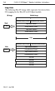
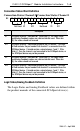
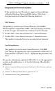
Connection
Enable W
ord Definition
Connection
Enable Channel
2
Connection Enable Channel 1
15 14 13 12 11 10 9 8 7 6 5 4 3 2 1 0
Bit:
Not Used E2 Not Used E1
Description
E1 SCANport channel 1 enable bit. When set to 1, the module will
attempt to connect to the SCANport device. When reset to 0, the
module stops communicating with the connected SCANport device.
This usually causes the device to fault.
E2 SCANport channel 2 enable bit. When set to 1, the module will
attempt to connect to the SCANport device. When reset to 0, the
module stops communicating with the connected SCANport device.
This usually causes the device to fault.
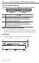
Logic
Command/Analog Reference Definition
The Logic Command and Analog Reference values are defined
within the product manuals of the connected SCANport device(s).
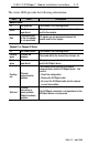
LED
Indicators
The status LEDs are located on the module’s top label.
SCANPORT
Flex I/O
1203-FM1
1
MODULE
CH1 CH2