
Manual

FLEX I/O SCANportt Module Installation Instructions
1–5
1203-5.7-- April 1996
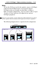
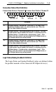
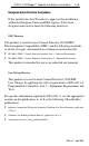
Connection
Status W
ord Definition
Connection Status Channel 2 Connection Status Channel 1
15 14 13 12 11 10 9 8 7 6 5 4 3 2 1 0
Bit:
Not Used V2 ID2 Not Used V1 ID1
Description
V1 SCANport channel 1 valid data bit. When high (1), the Logic Status
and Analog Feedback values are valid and can be used. When low
(0), the values should not be used.
ID1 SCANport channel 1 connected peripheral port ID number. This three
bit field contains the port number that channel 1 is connected to on the
SCANport device. It should contain a value between 1 and 7. If this
field is 7, then the channel is not connected to the SCANport device, or
the SCANport device may not be powered.
V2 SCANport channel 2 valid data bit. When high (1), the Logic Status
and Analog Feedback values are valid and can be used. When low
(0), the values should not be used.
ID2 SCANport channel 2 connected peripheral port ID number. This three
bit field contains the port number that channel 2 is connected to on the
SCANport device. It should contain a value between 1 and 7. If this
field is 7, then the channel is not connected to the SCANport device, or
the SCANport device may not be powered.
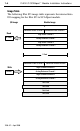
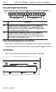
Logic
Status/Analog Feedback Definition
The Logic Status and Analog Feedback values are defined within
the product manuals of the connected SCANport device(s).