
Manual

FLEX I/O SCANportt Module Installation Instructions
1–4
1203-5.7-- April 1996
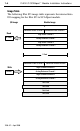
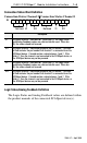
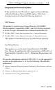
Image Table
The following Flex I/O image table represents the internal data
I/O mapping for the Flex I/O to SCANport module.
0
Connection
Status Channel 1
Logic Status Channel 1
Analog Feedback Channel 1
Logic Status Channel 2
Analog Feedback Channel 2
Connection Status Channel 2
Module Image
I/O Image
6 Words
5 W
ords
Read
Write
1 W
ord
Connection Enable Channel 2
Connection Enable Channel 1
Logic Command Channel 1
Analog Reference Channel 1
Logic Command Channel 2
Analog Reference Channel 2
Not Used
Not Used
Not Used
Not Used