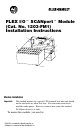
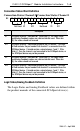
FLEX I/Ot SCANportt Module (Cat. No. 1203 FM1) Installation Instructions 1 2 7 0 8 6 1 2 3 4 3 6 4 Channel 1 S Channel 2 5 Module Installation Important: This module mounts on a special 1203 terminal base unit and should not be used with any other flex base. You can remove and insert modules under power. However, removal may cause the attached SCANport device(s) to fault. To mount this module, you need to: FLEX I/O is a trademark of Allen Bradley Co. Inc.
1–2 FLEX I/O SCANportt Module Installation Instructions 1. Rotate keyswitch (2) on terminal base unit (3) clockwise to position 1 as required for this type of module. 2. Make certain the flexbus connector (7) is pushed all the way to the left to connect with the neighboring terminal base/adapter. You cannot install the module unless the connector is fully extended. 3. Make sure that the pins on the bottom of the module are straight so they will align properly with the connector in the terminal base unit.
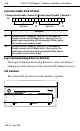
FLEX I/O SCANportt Module Installation Instructions 1–3 Wiring To wire the 1203 base used by this module, connect a SCANport cable from the SCANport device to the desired channel. SCANport cables are available in either Male–to–Male or Male–to–Female configurations. You can connect cables of up to 10 meters (33 feet) between a SCANport device and any SCANport peripheral.
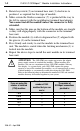
1–4 FLEX I/O SCANportt Module Installation Instructions Image Table The following Flex I/O image table represents the internal data I/O mapping for the Flex I/O to SCANport module.
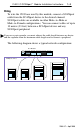
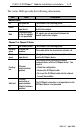
FLEX I/O SCANportt Module Installation Instructions 1–5 Connection Status Word Definition Connection Status Channel 2 Connection Status Channel 1 Bit: 15 14 13 12 11 10 9 Not Used V2 ID2 8 7 6 5 Not Used 4 3 V1 2 1 0 ID1 Description V1 SCANport channel 1 valid data bit. When high (1), the Logic Status and Analog Feedback values are valid and can be used. When low (0), the values should not be used. ID1 SCANport channel 1 connected peripheral port ID number.
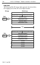
1–6 FLEX I/O SCANportt Module Installation Instructions Connection Enable Word Definition Connection Enable Channel 2 Connection Enable Channel 1 Bit: 15 14 13 12 11 10 9 Not Used 8 7 6 E2 5 4 3 2 Not Used 1 0 E1 Description E1 SCANport channel 1 enable bit. When set to 1, the module will attempt to connect to the SCANport device. When reset to 0, the module stops communicating with the connected SCANport device. This usually causes the device to fault. E2 SCANport channel 2 enable bit.
FLEX I/O SCANportt Module Installation Instructions 1–7 The status LEDs provide the following information: LED State Description Module Status Off Not powered The module is not receiving power. Green On-line, operational I/O signals are operational between the module and the flex adapter. Red Communications to the flex adapter is not operational I/O signals are not operational between the module and the flex adapter.
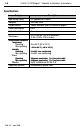
1–8 FLEX I/O SCANportt Module Installation Instructions Specifications Category Description Input voltage rating 5V supplied from Flexbus Indicators 3 bi-color LEDs Flexbus current 160mA maximum (refer to Attention on page 2) Power consumption 0.8W Keyswitch position 1 Dimensions 45.7H x 94.0W x 53.3D in millimeters (1.8H x 3.7W x 2.
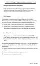
FLEX I/O SCANportt Module Installation Instructions 1–9 European Union Directive Compliance If this product has the CE mark it is approved for installation within the European Union and EEA regions. It has been designed and tested to meet the following directives.
1–10 FLEX I/O SCANportt Module Installation Instructions With major offices worldwide. World Headquarters, Allen Bradley, 1201 South Second Street, Milwaukee, WI 53204 USA, Tel: (1) 414 382 2000 Fax: (1) 414 382 4444 Publication 1203 5.8 - April 1996 1203-5.7-- April 1996 PN95654201 Copyright 1996 Allen Bradley Company, Inc.
1–46 FLEX I/O SCANportt Module Installation Instructions With major offices worldwide. World Headquarters, Allen Bradley, 1201 South Second Street, Milwaukee, WI 53204 USA, Tel: (1) 414 382 2000 Fax: (1) 414 382 4444 Publication 1203 5.8ML - April 1996 PN95654201 Copyright 1996 Allen Bradley Company, Inc.