
Owner manual


FLEX I/O SCANportt Base Installation Instructions
1–5
1203-5.7ML- April 1996
Wiring
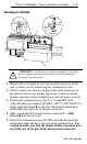
To wire the 1203–FB1 base, connect a SCANport cable from the
SCANport device to the desired channel. SCANport cables are
available in either Male–to–Male or Male–to–Female
configurations. You can connect cables of up to 10 meters (33
feet) between a SCANport device and any SCANport peripheral.
If you use a port expander, you must subtract the cable length
between any device and the expander from the maximum cable
length used to connect a peripheral.
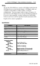
Specifications
Category Description
I/O capacity
2 SCANport channels
SCANport voltage rating
12V dc +10% - 25%
SCANport current
60mA per channel
Isolation voltage
1200V ac/dc Flex to SCANport channel
SCANport cable
8-pin circular mini-DIN connector
Keyswitch position 1
Dimensions (with the module
installed)
78.7H x 94.0W x 65.6D millimeters
(3.1H x 3.7W x 2.7D inches)
Environmental conditions
E
nv
i
ronmenta
l
con
di
t
i
ons
Temperature
Oi
Temperature
Operating
Non operating
0 to +55°
C (32 to 131
°F)
40 t 85
°
C ( 40 t 185
°F)
pg
Non-operating
Humidit
y
0
to
+55
C
(32
to
131
F)
-40 to +85
°
C (-40 to 185
°F)
H
um
idit
y
Operating
Nti
5 to 80% non-condensing
Operating
Non-operating
Shock
5
to
80%
non
-
condensing
5 to 95% non-condensing
pg
Shock
O
p
eratin
g
5 to 95% non condensing
30g peak acceleration, 1
1(±1)ms pulse width
Operating
Non-operating
Vibration
30g peak acceleration, 1
1(±1)ms pulse width
50g peak acceleration, 1
1(±1)ms pulse width
Non operating
Vibration
50g
peak
acceleration
,
1
1(±1)ms
pulse
width
5g @ 10-500Hz per IEC 68-2-6
5g @ 10 500Hz per IEC 68 2 6
Regulatory agencies
As specified by product label