203-EN1 EtherNet/IP-toSCANport Module FRN 1.
Important User Information Solid state equipment has operational characteristics differing from those of electromechanical equipment. “Safety Guidelines for the Application, Installation and Maintenance of Solid State Controls” (Publication SGI-1.1 available from your local Rockwell Automation Sales Office or online at http://www.ab.com/ manuals/gi) describes some important differences between solid state equipment and hard-wired electromechanical devices.
Summary of Changes This is the first release of the 1203-EN1 EtherNet/IP-to-SCANport module FRN 1.xxx.
S-ii Summary of Changes
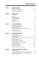
Table of Contents Preface About This Manual Related Documentation . . . . . . . . . . . . . . . . . . . . . . . . . . . . . P-1 Conventions Used in This Manual . . . . . . . . . . . . . . . . . . . . . P-2 Rockwell Automation Support. . . . . . . . . . . . . . . . . . . . . . . . P-2 Chapter 1 Getting Started Components . . . . . . . . . . . . . . . . . . . . . . . . . . . . . . . . . . . . . . Features . . . . . . . . . . . . . . . . . . . . . . . . . . . . . . . . . . . . . . . . .
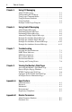
ii Table of Contents Chapter 5 Using I/O Messaging About I/O Messaging . . . . . . . . . . . . . . . . . . . . . . . . . . . . . . . Understanding the I/O Image. . . . . . . . . . . . . . . . . . . . . . . . . Using Logic Command/Status . . . . . . . . . . . . . . . . . . . . . . . . Using Reference/Feedback . . . . . . . . . . . . . . . . . . . . . . . . . . Using Datalinks . . . . . . . . . . . . . . . . . . . . . . . . . . . . . . . . . . . Example Ladder Logic Program . . . . . . . . . . . . . . . .
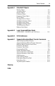
Table of Contents Appendix C iii EtherNet/IP Objects Identity Object . . . . . . . . . . . . . . . . . . . . . . . . . . . . . . . . . . . . C-2 Assembly Object . . . . . . . . . . . . . . . . . . . . . . . . . . . . . . . . . . C-4 Register Object. . . . . . . . . . . . . . . . . . . . . . . . . . . . . . . . . . . . C-6 Parameter Object . . . . . . . . . . . . . . . . . . . . . . . . . . . . . . . . . . C-8 Parameter Group Object. . . . . . . . . . . . . . . . . . . . . . . . . . . . C-11 PCCC Object .
iv Table of Contents
Preface About This Manual Topic Related Documentation Conventions Used in This Manual Rockwell Automation Support Page P-1 P-2 P-2 Related Documentation For: Refer to: Publication EtherNet/IP EtherNet/IP Planning and Installation Manual EtherNet/IP Performance and Application Guide ENET-IN001… ENET-AP001… DriveExplorer™ http://www.ab.com/drives/driveexplorer, and DriveExplorer Online help (installed with the software) — DriveExecutive™ http://www.ab.
P-2 About This Manual Conventions Used in This Manual The following conventions are used throughout this manual: • Parameter names are shown in the format Parameter xx - [*]. The xx represents the parameter number. The * represents the parameter name. For example Parameter 01 - [SCANport Adapter]. • Menu commands are shown in bold type face and follow the format Menu > Command. For example, if you read “Select File > Open,” you should click the File menu and then click the Open command.
About This Manual P-3 Technical Product Assistance If you need to contact Rockwell Automation, Inc. for technical assistance, please review the information in Chapter 7, Troubleshooting, first. If you still have problems, call your local Rockwell Automation, Inc. representative. U.S. Allen-Bradley Drives Technical Support: E-mail: support@drives.ra.rockwell.com Tel: (1) 262.512.8176 Fax (1) 262.512.2222 Online: www.ab.com/support/abdrives UK Customer Support Center: E-mail: esupport2@ra.rockwell.
P-4 Notes: About This Manual
Chapter 1 Getting Started The 1203-EN1 EtherNet/IP-to-SCANport module is a communication option intended for use with Allen-Bradley drives and other products that support SCANport. Topic Components Features Compatible Products Required Equipment Page 1-1 1-2 1-3 1-3 Topic Safety Precautions Quick Start Modes of Operation Page 1-4 1-5 1-6 Components Figure 1.
1-2 Getting Started Features The EtherNet/IP-to-SCANport module features the following: • The module is an external module only. It requires DC power from either an appropriate DC power source or AC-to-DC converter. Connectors for both are provided. • A number of configuration tools can be used to configure the module and connected drive. These include drive-configuration software tools such as DriveExplorer (version 4.03 or higher) or DriveExecutive (version 3.01 or higher).
Getting Started 1-3 Compatible Products The EtherNet/IP-to-SCANport module is compatible with Allen-Bradley drives and other products that support SCANport. SCANport is a standard peripheral communication interface.
1-4 Getting Started Safety Precautions Please read the following safety precautions carefully. ! ! ! ! ! ! ATTENTION: Risk of injury or equipment damage exists. Only personnel familiar with drive and power products and the associated machinery should plan or implement the installation, start-up, configuration, and subsequent maintenance of the product using an EtherNet/IP module. Failure to comply may result in injury and/or equipment damage. ATTENTION: Risk of equipment damage exists.
Getting Started 1-5 Quick Start This section is provided to help experienced users quickly start using the EtherNet/IP module. If you are unsure how to complete a step, refer to the referenced chapter. Step 1 Review the safety precautions for the module. 2 3 4 5 6 7 Verify that the drive is properly installed. Install the module. Panel or DIN rail mount the module. Verify that the drive is not powered.
1-6 Getting Started Modes of Operation The module uses four status indicators to report its operating status. They can be viewed on the 1203-EN1 enclosure cover. See Figure 1.2. Figure 1.2 Status Indicators Front View ➍ ➌ ➋ ➊ PORT MOD NET A 1203-EN1 NET B EtherNet/IP to SCANport 10/100 Mbps Item Status Normal Description Indicator Status (1) ➊ PORT Green Normal Operation. The module is properly connected and is communicating with the drive. ➋ MOD Green Normal Operation.
Chapter 2 Installing the Module Chapter 2 provides instructions for installing the module.
Installing the Module Set the Web Pages Switch (SW2) to enable or disable the module web pages (see Figure 2.1 and setting descriptions below). By default, the module web pages are disabled. For complete details on module web pages, see Chapter 8, Viewing the Module’s Web Pages. Figure 2.1 Setting Web Pages Switch UNUSED SWITCH Disable Web Position Enable Web Position WEB PAGES SWITCH O1 2 N ! ATTENTION: Risk of equipment damage exists.
Installing the Module 2-3 Mounting the Module ! ATTENTION: Risk of equipment damage exists. During panel or DIN rail mounting, be sure that all debris (metal chips, wire strands, etc.) is kept from falling into the module enclosure. Debris that falls into the enclosure could cause damage on power up. Panel or DIN rail mount the module before connecting the module to the network and drive. Minimum Spacing 1203-EN1’s can be zero-stacked (side-by-side mounting). Allow 75 mm (3 in.
2-4 Installing the Module Panel Mounting Procedure Using Module as a Template The following procedure enables you to use the assembled module as a template for drilling holes in the panel. 1. Using the assembled module as a template, carefully mark the center of both holes on the panel. 2. Remove the module to a clean location. 3. Drill and tap the mounting holes for the recommended M4 or #8 panhead screws (supplied separately). 4. Place the module back on the panel, and check for proper hole alignment.
Installing the Module 2-5 Connecting the Module to the Network and Drive ! ATTENTION: Risk of injury or death exists. The drive may contain high voltages that can cause injury or death. Remove power from the drive, and then verify power has been discharged before installing or removing an module. ! ATTENTION: Risk of equipment damage, injury or death exists. Unpredictable operation may occur if you fail to verify that parameter settings are compatible with your application.
2-6 Installing the Module Applying Power ! ATTENTION: Risk of equipment damage, injury, or death exists. Unpredictable operation may occur if you fail to verify that parameter settings are compatible with your application. Verify that settings are compatible with your application before applying power to the drive. The 1203-EN1 module requires DC power from either an appropriate DC power source or an AC-to-DC converter. Connectors for both are provided.
Installing the Module 2-7 Figure 2.5 Powering Multiple Modules via Daisy Chaining 1203-EN1 Modules + - + - + - ... - or - DC Power Source AC-to-DC Converter + - The number of 1203-EN1’s that can be daisy-chained together is dependent on the available output capacity of the DC power source or AC-to-DC converter. The following example illustrates how to determine the number of daisy-chained 1203-EN1’s that can be powered.
2-8 Installing the Module Commissioning the Module To commission the module, you must set a unique IP address. (Refer to the Glossary for details about IP addresses.) After installing the module and applying power, you can set the IP address by using a BOOTP server or by setting module parameters. By default, the module is configured so that you must set the IP address using a BOOTP server. To set the IP address using module parameters, you must disable the BOOTP feature.
Chapter 3 Configuring the Module Chapter 3 provides instructions and information for setting the parameters in the module.
3-2 Configuring the Module Using DriveExplorer Software DriveExplorer can be used with the 1203-EN1 via two connection methods: RS-232 Serial and EtherNet/IP. RS-232 Serial (DriveExplorer Lite and Full versions) A 1203-SFC cable (comes with 1203-SSS AnaCANda and available separately) is used to connect a PC to the DF1 serial port on the 1203-EN1. The user can adjust parameters on the 1203-EN1 and the connected Host drive.
Configuring the Module 3-3 Using BOOTP By default, the module is configured so that you can set its IP address, subnet mask, and gateway address by using a BOOTP utility. You can select from a variety of BOOTP utilities. These instructions use Rockwell’s BOOTP Server (version 2.1), a stand-alone program that incorporates the functionality of standard BOOTP utilities with a graphical interface. It is available from http://www.ab.com/networks.
3-4 Configuring the Module The New Entry dialog box appears. Figure 3.3 New Entry Dialog Box 4. Enter in the following data: Box (1) IP Address Subnet Mask Gateway (1) Type A unique IP address for the module The subnet mask for the module’s network The IP address of the gateway device on the module’s network For definitions, refer to the Glossary. 5. Click OK to apply the settings. The module appears in the Relation List with the new settings. Figure 3.
Configuring the Module 3-5 Setting the IP Address, Subnet Mask, and Gateway Address By default, the module is configured so that you set its IP address, subnet mask, and gateway address using a BOOTP server. If you want to set these features using the module’s parameters instead, you must disable BOOTP and then set the appropriate parameters in the module using a serial connection. DriveExplorer (version 4.03) was used for set up examples in this chapter.
3-6 Configuring the Module 3. Reset the module. See Resetting the Module section in this chapter. The Net A status indicator will be solid green or flashing green if the IP address is correctly configured. To set a subnet mask using parameters 1. Verify that Parameter 02 - [BOOTP] is set to Disabled. This parameter must be set to Disabled to configure the subnet mask using parameters. 2. Set the value of Parameters 07 - [Subnet Cfg 1] through 10 [Subnet Cfg 4] to the desired value for the subnet mask.
Configuring the Module 3-7 Setting the Data Rate By default, the module is set to autodetect, so it automatically detects the data rate and duplex setting used on the network. If you need to set a specific data rate and duplex setting, the value of Parameter 27 - [EN Rate Cfg] determines the Ethernet data rate and duplex setting that the module will use to communicate. For definitions of data rate and duplex, refer to the Glossary. 1.
3-8 Configuring the Module drive to “Adapter 2” so that the drive uses the Reference from the module. Also, verify that the mask parameters (for example, Parameter 92 - [Logic Mask]) in the drive are configured to receive the desired logic from the module. Refer to the documentation for your drive for details. 3. If you enabled one or more Datalinks, configure parameters in the drive to determine the source and destination of data in the Datalink(s).
Configuring the Module 3-9 Selecting Master-Slave or Peer-to-Peer A hierarchy determines the type of device with which the module exchanges data. In a Master-Slave hierarchy, a module exchanges data with a master, such as a scanner or bridge. In a Peer-to-Peer hierarchy, a module exchanges data with one or more EtherNet/IP modules connected to devices that have compatible Logic Command/Status words.
3-10 Configuring the Module 4. Reset the module. See Resetting the Module section in this chapter. The module is ready to receive I/O from the master (i.e., scanner). You must now configure the scanner to recognize and transmit I/O to the module. Refer to Chapter 4, Configuring the Scanner or Bridge. To set a module to transmit Peer-to-Peer data 1. Verify that Parameter 61 - [Peer Out Enable] is set to Off. This parameter must be Off while you configure peer output parameters. Table 3.
Configuring the Module – 3-11 The maximum interval ensures that the module transmits messages often enough so that the receiving module(s) can receive recent data and verify that communications are working or, if communications are not working, can timeout. The maximum interval is the value of Parameter 62 - [Peer Out Time] multiplied by the value of Parameter 63 - [Peer Out Skip], which has a default of 1. For example, suppose the minimum interval (Parameter 62 - [Peer Out Time]) is set to 2.
3-12 Configuring the Module 3. Select the destination of the data that is input to the drive as Peer A in Parameter 48 - [Peer A Input]. Table 3.J Parameter 48 - [Peer A Input] Setup Values Value 0 1 2-5 Description Off (Default) Logic Command/Reference Datalink A, B, C, or D Input 4. If desired, select the destination of the data to input to the drive as Peer B in Parameter 49 - [Peer B Input]. Table 3.
Configuring the Module 3-13 4.00), then Parameter 56 - [Peer Inp Timeout] needs to have a value greater than 4.00, such as 5.00. 7. Set the action in Parameter 51 - [Peer Flt Action] that the module will take if it times out. ! ATTENTION: Risk of injury or equipment damage exists. Parameter 51 - [Peer Flt Action] lets you determine the action of the module and connected drive if communications are disrupted. By default, this parameter faults the drive.
3-14 Configuring the Module ! ATTENTION: Risk of injury or equipment damage exists. Parameters 30 - [Comm Flt Action] and 31 - [Idle Flt Action] let you determine the action of the module and connected drive if communications are disrupted or the scanner is idle. By default, these parameters fault the drive. You can set these parameters so that the drive continues to run. Precautions should be taken to ensure that the settings of these parameters do not create a risk of injury or equipment damage.
Configuring the Module 3-15 Setting Web Features Access By accessing the IP address set for the module using a web browser, you can view the module’s web pages for information about the module and the drive to which it is connected. Additionally, the module can be configured to automatically send e-mail messages to desired addresses when selected drive faults occur and/or are cleared, and/or when the module takes a communication or idle fault action.
3-16 Configuring the Module Resetting the Module Changes to switch settings and some module parameters require that you reset the module before the new settings take effect. You can reset the module by cycling power to the module or by using the following parameter: ! ATTENTION: Risk of injury or equipment damage exists. If the module is transmitting control I/O to the drive, the drive may fault when you reset the module. Determine how your drive will respond before resetting a connected module.
Configuring the Module 3-17 Viewing the Module Configuration The following parameters provide information about how the module is configured. You can view these parameters at any time using DriveExplorer (version 4.03 or higher) or DriveExecutive (version 3.01 or higher) software. Param Number 28 15 – 18 19 – 22 23 – 26 33 Name EN Rate Act IP Addr Act 1 – 4 Subnet Act 1 – 4 Gateway Act 1 – 4 SP I/O Act 58 Peer Inp Status Description The data rate used by the module.
3-18 Notes: Configuring the Module
Chapter 4 Configuring the Scanner or Bridge Chapter 4 provides instructions on how to configure a ControlLogix bridge to communicate with the module and connected 1305 drive. Topic Example Network Adding a Bridge or Scanner to the I/O Configuration Adding the Module and Drive to the I/O Configuration Saving the Configuration Page 4-1 4-2 4-4 4-7 Example Network After the module is configured, the connected drive and module will be a single node on the network.
4-2 Configuring the Scanner or Bridge Adding a Bridge or Scanner to the I/O Configuration To establish communications over an EtherNet/IP network, you must first add the controller and its scanner or bridge to the I/O configuration. 1. Start RSLogix 5000. The RSLogix 5000 window appears. Figure 4.2 RSLogix 5000 Window 2. In the Control Organizer pane, right-click the I/O Configuration folder and select New Module (Figure 4.2). The Select Module Type dialog box (Figure 4.3) appears. Figure 4.
Configuring the Scanner or Bridge 4-3 3. In the list, select the EtherNet/IP scanner or bridge used by your controller and then select the major revision of its firmware in the Major Revision box. In this example (Figure 4.3), we use a 1756-ENBT EtherNet/IP Bridge (Series B), so the 1756-ENBT/B option is selected. 4. Click OK. The Module Properties dialog box (Figure 4.4) appears. Figure 4.4 Module Properties Dialog Box - Page 1 5.
4-4 Configuring the Scanner or Bridge Adding the Module and Drive to the I/O Configuration To transmit data between the scanner or bridge and the module, you must add the 1203-EN1 module as a child device of the scanner or bridge. 1. In the Control Organizer pane, right-click on the scanner or bridge and select New Module (Figure 4.6). In our example, we right-click on the 1756-ENBT/B bridge. Figure 4.6 Right-Clicking on the Scanner The Select Module Type dialog box (Figure 4.7) appears. Figure 4.
Configuring the Scanner or Bridge 4-5 Figure 4.8 Module Properties Dialog Box - Page 1 3. Edit the following information about the module: Box Type Name A name to identify the module and drive. Comm. Format Data - INT. This setting formats the data in 16-bit words. IP Address The IP address of the module. 4. Under Connection Parameters, edit the following: Box Input Output Configuration Assembly Instance Size 1 The value will vary based on your (This value is required.
4-6 Configuring the Scanner or Bridge TIP: For instructions on configuring the I/O for the module (Parameter 32 - [SP I/O Cfg]) and the Master-Slave Hierarchy (Parameters 45 - [M-S Input] and 46 - [M-S Output]), refer to Chapter 3, Configuring the Module. 5. Click Next > to display the next page. Figure 4.9 Module Properties Dialog Box - Page 2 6. In the Requested Packet Interval (RPI) box, set the value to 5.0 milliseconds or greater.
Configuring the Scanner or Bridge 4-7 Saving the Configuration After adding the scanner or bridge and the module to the I/O configuration, you must download the configuration to the controller. You should also save the configuration to a file on your computer. 1. Select Communications > Download. The Download dialog box (Figure 4.11) appears. Figure 4.
4-8 Notes: Configuring the Scanner or Bridge
Chapter 5 Using I/O Messaging Chapter 5 provides information and examples that explain how to use a ControlLogix controller to send I/O Messaging to control, configure, and monitor a SCANport-based drive. A 1305 drive is used for the examples in this chapter. Topic About I/O Messaging Understanding the I/O Image Using Logic Command/Status ! Page 5-1 5-2 5-3 Topic Using Reference/Feedback Using Datalinks Example Ladder Logic Program Page 5-4 5-5 5-5 ATTENTION: Risk of injury or equipment damage exists.
5-2 Using I/O Messaging Understanding the I/O Image The terms input and output are defined from the scanner’s point of view. Therefore, Output I/O is data produced by the scanner and consumed by the EtherNet/IP module. Input I/O is status data that is produced by the module and consumed as input by the scanner. The I/O image table will vary based on the following: • Configuration of I/O (Parameter 32 - [SP I/O Cfg]). If any of the I/O is not enabled, the image table is truncated.
Using I/O Messaging 5-3 Figure 5.2 illustrates an example of an I/O image that does not use all of the I/O data. Only the Logic Command/Reference and Datalink B are enabled. Figure 5.
5-4 Using I/O Messaging Using Reference/Feedback When enabled, Reference begins at word 1 (16-bit) in the Output image and Feedback begins at word 3 in the Input image. The Reference (16 bits) is produced by the controller and consumed by the module. The Feedback (16 bits) is produced by the module and consumed by the controller. The Reference value is a scaled value; it is not an engineering value.
Using I/O Messaging 5-5 Using Datalinks A Datalink is a mechanism used by SCANport drives to transfer data to and from the controller. Datalinks allow parameter values to be changed without using an Explicit Message. When enabled, each Datalink occupies two 16-bit words in both the input and output image. Rules for Using Datalinks • Each set of Datalink parameters in a SCANport drive can be used by only one module.
5-6 Using I/O Messaging Example Parameter Settings in the Drive Example Parameter Settings in the Module
Using I/O Messaging 5-7 RSLogix 5000 Configuration Controller Tags When you add the module and drive to the I/O configuration (refer to Chapter 4), RSLogix 5000 automatically creates controller tags for them. You can expand the Output and Input tags to reveal the output and input configuration. The Output tag for this example program requires ten 16-bit words of data and the Input tag for this example requires twelve 16-bit words of data (see Figure 5.3). Figure 5.
5-8 Using I/O Messaging Figure 5.4 MainProgram Tags for the Example Ladder Program Logic Command/Status Words This example uses the Logic Command word and Logic Status word for a 1305 drive. Refer to Appendix D, Logic Command/Status Words, to view these. The definition of the bits in these words may vary if you are using a different SCANport product. Refer to the documentation for your product.
Using I/O Messaging 5-9 Example ControlLogix Ladder Logic Program Figure 5.5 Example ControlLogix Ladder Logic Program for I/O Messaging ControlLogix to 1305 drive on EtherNet/IP The ControlLogix system consists of a 1756-ENBT in slot 5 communicating over EtherNet/IP with a 1305 drive using a 1203-EN1 EtherNet/IP module. The I/O image is as follows: INPUT (12 INT words) AB1305_Drive:I.Data[0] = ENBT Overhead AB1305_Drive:I.Data[1] = ENBT Overhead AB1305_Drive:I.Data[2] = Drive Logic Status AB1305_Drive:I.
5-10 Using I/O Messaging Figure 5.5 Example ControlLogix Ladder Logic Program for I/O Messaging (Cont.) This rung displays the Feedback word from the 1305 drive. Note that the value is in an engineering unit, where "32,767" equals the Parameter 19 [Maximum Freq] value and "0" equals 0 Hz. The relationship is linear. For example, if Parameter 19 = 60 Hz (default setting), then: 32,767 = 60 Hz 16,384 = 30 Hz 8,192 = 15 Hz 4,096 = 7.5 Hz 0 = 0 Hz (etc.) 1305 Feedback MOV Move Source AB1305_Drive:I.
Using I/O Messaging 5-11 Figure 5.5 Example ControlLogix Ladder Logic Program for I/O Messaging (Cont.) 1305 Logic Command FORWARD AB1305_Drive:O.Data[0].4 Forward_Command 11 12 1305 Logic Command REVERSE AB1305_Drive:O.Data[0].5 Forward_Command / This rung provides the Reference word to the 1305 drive. Note that the value is in an engineering unit, where "32,767" equals the Parameter 19 [Maximum Freq] value and "0" equals 0 Hz. The relationship is linear.
5-12 Using I/O Messaging Example Datalink Data The following figure shows the Datalink data used in the example program. Figure 5.
Chapter 6 Using Explicit Messaging Chapter 6 provides information and examples that explain how to use Explicit Messaging to read/write parameters on a SCANport-based drive. The examples used in this chapter are a continuation of the 1305 drive ladder example in Chapter 5.
6-2 Using Explicit Messaging Formatting Explicit Messages Explicit Messages for the ControlLogix Controller ControlLogix scanners and bridges accommodate both downloading Explicit Message Requests and uploading Explicit Message Responses. The scanner or bridge module can accommodate one request or response for each transaction block. Each transaction block must be formatted as shown in Figure 6.1. Figure 6.
Using Explicit Messaging 6-3 ControlLogix Message Requests and Responses Box Description ➊ Message Type The message type is usually CIP Generic. ➋ Service Type The service type indicates the service (for example, Get Attribute Single or Set Attribute Single) that you want to perform. Available services depend on the class and instance that you are using. Refer to Appendix C, EtherNet/IP Objects. ➌ Service Code The service code is the code for the requested EtherNet/IP service.
6-4 Using Explicit Messaging Performing Explicit Messages There are five basic events in the Explicit Messaging process. The details of each step will vary depending on the controller. Refer to the documentation for your controller. Important: There must be a request message and a response message for all Explicit Messages, whether you are reading or writing data. Figure 6.
Using Explicit Messaging 6-5 About the Example Explicit Messages These examples show how to format and execute the following types of Explicit Messages using a ControlLogix controller: • Get Attribute Single • Set Attribute Single • Get Attributes Scattered • Set Attributes Scattered Message Formats When formatting an example message, refer to Formatting Explicit Messages in this chapter for an explanation of the content of each box.
6-6 Using Explicit Messaging Example Get Attribute Single Message A Get Attribute Single message reads a single attribute value. In this example, we read the value of a parameter in a 1305 drive. Example Message Format Figure 6.4 Message Format for a Get Attribute Single Message The following table identifies key settings for the message format: Configuration Service Type (1) Service Code (1) Class Instance Attribute Destination (1) Value Get Attribute Single e (Hex.) f (Hex.) 74 (Dec.) 1 (Hex.
Using Explicit Messaging 6-7 Example Ladder Logic Rung Figure 6.5 Example Get Attribute Single Message Explicit Messaging Examples 15 Reading a single parameter (Get Attribute Single command). In this example, Parameter 74 [Preset Freq 5] is read. PerformParameterRead MSG Type - CIP Generic EN DN Message Control ParameterReadMessage ...
6-8 Using Explicit Messaging Example Set Attribute Single Message A Set Attribute Single message writes a value for a single attribute. In this example, we write the value of a parameter in a 1305 drive. Example Message Format Figure 6.6 Message Format for a Set Attribute Single Message The following table identifies key settings for the data format: Configuration Service Type (1) Service Code (1) Class Instance Attribute Source Element Source Length (1) Value Set Attribute Single 10 (Hex.) f (Hex.
Using Explicit Messaging 6-9 Example Ladder Logic Rung Figure 6.7 Example Set Attribute Single Message 16 Writing a single parameter (Set Attribute Single command). In this example, Parameter 74 [Preset Freq 5] is written. PerformParameterWrite MSG Type - CIP Generic EN DN Message Control ParameterWriteMessage ... ER Example Source Data In this example, the Set Attribute Single message writes the value in the source tag named ParameterWriteValue to Parameter 74 - [Preset Freq 5] in the 1305 drive.
6-10 Using Explicit Messaging Example Get Attributes Scattered Message A Get Attributes Scattered message reads the values of multiple attributes. In this example, we read the values of various parameters in a 1305 drive. Example Message Format Figure 6.
Using Explicit Messaging 6-11 Example Ladder Logic Rung Figure 6.9 Example Get Attributes Scattered Message 17 Reads a scattered group of parameters (not a contiguous block). PerformScatteredRead Type - CIP Generic Message Control MSG ScatteredReadMessage ... EN DN ER Explanation of Source and Destination Data The data structures in Figure 6.10 uses 16-bit words and can get up to 40 parameters in a single message.
6-12 Using Explicit Messaging Example Data In this example, we use the data structure in Figure 6.11 in the source tag named ScatteredReadRequest to read the following four parameters: Parameter 54 - [Output Current], 1 - [Output Voltage], 53 - [DC Bus Voltage], and 4 - [Last Fault]. The Get Attributes Scattered message reads the multiple parameters and returns their values to the destination tag (ScatteredReadResponse). Figure 6.
Using Explicit Messaging 6-13 Example Set Attributes Scattered Message A Set Attributes Scattered message writes values to multiple attributes. In this example, we write the values of various parameters in a 1305 drive. Example Message Format Figure 6.12 Message Format for a Set Attributes Scattered Message The following table identifies key settings for the message format: Configuration Service Type Service Code Class Instance Attribute Source Element Source Length Destination Value Custom 34 93 (Hex.
6-14 Using Explicit Messaging Example Ladder Logic Rung Figure 6.13 Example Set Attributes Scattered Message 18 Writes a scattered group of parameters (not a contiguous block). PerformScatteredWrite Type - CIP Generic Message Control MSG ScatteredWriteMessage ... EN DN ER Explanation of Source and Destination Data The data structures in Figure 6.14 use 16-bit words and can set up to 40 parameters in a single message.
Using Explicit Messaging 6-15 Example Data In this example, we use the data structure in Figure 6.15 in the source tag (ScatteredWriteRequest) to write new values for the following four parameters: Parameter 30 - [Accel Time 2] 75 - [Preset Freq 6] 31 - [Decel Time 2] 76 - [Preset Freq 7] Value 5.5 Sec. 60.01 Hz. 5.5 Sec. 70.01 Hz. The results of the message appear in the destination tag named ScatteredWriteResponse. Values of “0” indicate no errors occurred. Figure 6.
6-16 Notes: Using Explicit Messaging
Chapter 7 Troubleshooting Chapter 7 provides information for diagnosing and troubleshooting potential problems with the module. Topic Locating the Status Indicators PORT Status Indicator MOD Status Indicator Page 7-1 7-2 7-3 Topic Net A Status Indicator Net B Status Indicator Viewing and Clearing Events Page 7-4 7-5 7-6 Locating the Status Indicators The EtherNet/IP-to-SCANport module has four status indicators. They can be viewed when the 1203-EN1 enclosure cover is installed or removed. See Figure 7.
7-2 Troubleshooting PORT Status Indicator Status Off Flashing Red Solid Red Cause Corrective Action The module is not powered or • Securely connect the module to the drive using a 1202-Cxx Communication cable. is not connected properly to the drive. • Apply power to the module. The module is not receiving a • Verify that the 1202-Cxx Communication cable is securely connected. ping message from the drive. The drive has refused an I/O connection from the module. • Cycle power to the drive and/or module.
Troubleshooting 7-3 MOD Status Indicator Status Off Cause The module is not powered. Flashing Red The module has failed the firmware test. The module is being flash upgraded. Solid Red The module has failed the hardware test. Flashing Green The module is operational, but is not transferring I/O data. Corrective Action • Securely connect the module to the drive using a 1202-Cxx Communication cable. • Apply power to the module. • Clear faults in the module. • Cycle power to the drive and/or module.
7-4 Troubleshooting Net A Status Indicator Status Off Solid Red Flashing Red Cause Corrective Action • Securely connect the module to the drive using a The module is not 1202-Cxx Communication cable. powered, the module is not connected properly to the • Securely connect the Ethernet cable to the Ethernet network, or the module connector. needs an IP address. • Set a unique IP address using a BOOTP server or by disabling BOOTP and using parameters. • Apply power to the drive and module.
Troubleshooting 7-5 Net B Status Indicator Status Off Cause Corrective Action The module is not powered If Net A is off: or is not transmitting on the • Securely connect the module to the drive using a EtherNet/IP network. 1202-Cxx Communication cable. • Securely connect the Ethernet cable to the Ethernet connector. • Set a unique IP address using a BOOTP server or by disabling BOOTP and using parameters. If Net A is solid red: • Configure the module to use a unique IP address and cycle power.
7-6 Troubleshooting Viewing and Clearing Events The module maintains an event queue that reports the history of its actions. You can view the event queue using DriveExplorer (4.03 or higher) or DriveExecutive (3.01 or higher) software. Events Many events in the Event queue occur under normal operation. If you encounter unexpected communications problems, the events may help you or Allen-Bradley personnel troubleshoot the problem.
Troubleshooting Code 23 24 25 26 27 28 29 30 31 32 33 34 35 36 37 38 39 40 41 42 Event Net Comm Flt Net Sent Reset Net Close Flt Net Idle Flt Net Open 7-7 Description The module detected a communications fault on the network. The module received a reset from the network. An I/O connection from the network to the module was closed. The module is receiving “Idle” packets from the network. An I/O connection to the module from the network has been opened.
7-8 Notes: Troubleshooting
Chapter 8 Viewing the Module’s Web Pages Chapter 8 provides instructions on how to monitor the module and connected SCANport drive using the module’s web interface. Topic Accessing the Module’s Web Home Page Process Display Pop-up Windows TCP/IP Configuration Web Page Configure E-mail Notification Web Page SCANport Device Information Pages Page 8-1 8-5 8-6 8-7 8-9 Future enhancements may result in web pages that look different than the examples shown in this chapter.
8-2 Viewing the Module’s Web Pages To view the web pages of the module 1. On a computer with access to the EtherNet/IP network on which the module is installed, launch a web browser such as Microsoft Internet Explorer (version 5.0 or higher) or Netscape® Navigator® (version 4.6 or higher). The computer can access the module web pages if it is connected to the same network as the module, or if it is connected to a network with access to the module’s network via a gateway device (for example, a router). 2.
Viewing the Module’s Web Pages 8-3 Title Bar on Module Web Pages The title bar appears on all module web pages, including its Home Page. It consists of three elements: Item Description Allen-Bradley logo (at far left) This logo is also a link. Click it to view the ab.com web Home Page. Module Title (middle) Shows the module type and title. Rockwell Automation logo This logo is also a link. Click it to view the Rockwell (at far right) Automation web Home Page.
8-4 Viewing the Module’s Web Pages Link/Folder Description Launch my DriveExecutive software link Click this link to launch the DriveExecutive software already installed on your PC. E-mail technical support link Click this link to view a new e-mail message window to send a message to Allen-Bradley’s Technical Support Team.
Viewing the Module’s Web Pages 8-5 Process Display Pop-up Windows The Process Display pop-up window dynamically shows the SCANport product’s information. To view this window, click the “Process Display” link in the navigation menu. Figure 8.2 Example of Process Display Pop-up Window for SCANport Product Information Product text Status Commanded direction Rotation direction Process status (1) Description Description of SCANport product. Status of SCANport product.
8-6 Viewing the Module’s Web Pages TCP/IP Configuration Web Page The TCP/IP Configuration web page provides details about the module’s Ethernet settings and network activities. Figure 8.3 Example of TCP/IP Configuration Web Page Information IP Address Subnet Mask Gateway Address BOOTP Description IP address of the module. Subnet mask for the module’s network. Address for the gateway device on the module’s network. Whether BOOTP is being used to configure the module’s network information.
Viewing the Module’s Web Pages 8-7 Configure E-mail Notification Web Page The Configure E-mail Notification web page contains selections and data fields for configuring the module to automatically send e-mail messages to desired addresses when selected types of events occur. By default, this configuration is not protected. After configuration, the settings can be protected by setting the Parameter 65 - [Web Features] E-mail Cfg Bit 0 value to “0” (Disabled).
8-8 Viewing the Module’s Web Pages numbers in the box. 2. Click the module’s desired communication and/or idle fault action check boxes you want to occur that will send e-mail notification. 3. Type the following information in their respective boxes: Information “IP address of …” “E-mail addresses to notify …” “Subject of e-mail message …” Description Type in the address of the mail server that will be used to deliver the e-mail messages. Type in addresses to where you want e-mail messages to be sent.
Viewing the Module’s Web Pages 8-9 SCANport Device Information Pages SCANport device information pages show a device’s module information, and a fault and/or warning queue (for drive only) or event queue (for module only). Figure 8.6 and Figure 8.7 respectively show module information and fault queue example pages for the Port 0 device (host). Figure 8.8 shows an event queue example page for the Port 2 device (1203-EN1 module). Figure 8.
8-10 Viewing the Module’s Web Pages Figure 8.7 Example of Port 0 (1336 Plus II Drive) Fault Queue Page Figure 8.
Appendix A Specifications Appendix A presents the specifications for the module.
A-2 Specifications Environmental Temperature Operating Storage Relative Humidity Atmosphere Shock Operational Non-Operational Vibration Operational Non-Operational -10 to 50° C (14 to 149° F) -40 to 85° C (-40 to 185° F) 5 to 95% non-condensing Important: Module must not be installed in an area where the ambient atmosphere contains volatile or corrosive gas, vapors or dust.
Appendix B Module Parameters Appendix B provides information about the EtherNet/IP-to-SCANport module parameters. Topic Page About Parameter Numbers B-1 Parameter List B-1 About Parameter Numbers The parameters in the module are numbered consecutively. However, depending on which configuration tool you use, they may have different numbers. Configuration Tool • DriveExplorer • DriveExecutive • Explicit Messaging Numbering Scheme The module parameters begin with parameter 01.
B-2 Module Parameters Parameter No. Name and Description 03 [IP Addr Cfg 1] 04 [IP Addr Cfg 2] 05 [IP Addr Cfg 3] 06 [IP Addr Cfg 4] Sets the bytes of the IP address. 255 . 255 . 255 .
Module Parameters Parameter No. Name and Description 15 [IP Addr Act 1] 16 [IP Addr Act 2] 17 [IP Addr Act 3] 18 [IP Addr Act 4] Displays the actual IP address being used by the module. 255 . 255 . 255 .
B-4 Module Parameters Parameter No. Name and Description 28 [EN Rate Act] Displays the data rate actually used by the module. Details Default: Values 29 Type: Default: Values [Reset Module] No action if set to “Ready.” Resets the module if set to “Reset Module.” Restores the module to its factory default settings if set to “Set Defaults.” This parameter is a command. It will be reset to “Ready” after the command has been performed.
Module Parameters Parameter No. Name and Description Details 32 [SP I/O Cfg] Default: Sets the I/O that is transferred through the module. Bit Values: Bit 7 6 5 4 3 2 1 0 Default x x x 0 0 0 0 1 33 34 Type: Reset Required: Bit Definitions 0 = Cmd/Ref 1 = Datalink A 2 = Datalink B 3 = Datalink C 4 = Datalink D 5 = Not Used 6 = Not Used 7 = Not Used Default: Bit Values: [SP I/O Act] Displays the I/O that the module is actively transmitting.
B-6 Module Parameters Parameter No. Name and Description 36 [Flt Cfg A1 In] 37 [Flt Cfg A2 In] 38 [Flt Cfg B1 In] 39 [Flt Cfg B2 In] 40 [Flt Cfg C1 In] 41 [Flt Cfg C2 In] 42 [Flt Cfg D1 In] 43 [Flt Cfg D2 In] Sets the data that is sent to the Datalink in the drive if any of the following is true: • Parameter 30 - [Comm Flt Action] is set to “Send Flt Cfg” and communications are disrupted.
Module Parameters Parameter No. Name and Description 46 [M-S Output] Sets the Master-Slave output data. This data is produced by the module and consumed by the scanner. Bit 7 6 5 4 3 2 1 0 Default x x x 0 0 0 0 1 47 [Ref Adjust] Sets the percent scale factor for the Reference from the network. ! 48 49 Details Default: Bit Values: ATTENTION: To guard against equipment damage and/or personal injury, note that changes to Parameter 47 - [Ref Adjust] take effect immediately.
B-8 Module Parameters Parameter No. Name and Description 51 [Peer Flt Action] Sets the action that the module and drive take if the module detects that the Ethernet/IP communications with a peer have been disrupted. This setting is effective only if I/O is transmitted through the module. ! 52 53 54 55 Details Default: Values: Type: Reset Required: 0 = Fault 0 = Fault 1 = Zero Data 2 = Hold Last 3 = Send Flt Cfg Read/Write No ATTENTION: Risk of injury or equipment damage exists.
Module Parameters Parameter No. Name and Description 57 [Peer Inp Enable] Determines if Peer I/O input is on or off. Details Default: Values: B-9 63 Important: Changes to these parameters are ignored when Parameter 61 - [Peer Out Enable] is On. [Peer Out Skip] Determines the maximum time that a module will wait when transmitting data to a peer. The value of Parameter 62 - [Peer Out Time] is multiplied by the value of this parameter to set the time.
B-10 Module Parameters Parameter No. Name and Description 65 [Web Features] Sets the access to the Web interface and Web-configurable features.
Appendix C EtherNet/IP Objects Appendix C presents information about the EtherNet/IP objects that can be accessed using Explicit Messages. For information on the format of Explicit Messages and example ladder logic programs, refer to Chapter 6, Using Explicit Messaging. Object Identity Object Assembly Object Register Object Parameter Object Parameter Group Object PCCC Object Class Code Hex. Dec.
C-2 EtherNet/IP Objects Identity Object Class Code Hexadecimal 0x01 Decimal 1 Instances The number of instances depends on the number of components in the device connected to the module. This number of components can be read in Instance 0, Attribute 2.
EtherNet/IP Objects Identity Object (Continued) Services Service Code 0x01 0x05 0x0E Implemented for: Class Instance Yes Yes Yes Yes Yes Yes Service Name Get_Attributes_All Reset Get_Attribute_Single C-3
C-4 EtherNet/IP Objects Assembly Object Class Code Hexadecimal 0x04 Decimal 4 Instances Instance 1 2 Description All I/O data being read from the SCANport product (read-only) All I/O data written to the SCANport product (read/write) Class Attributes Attribute ID 1 2 100 Access Rule Get Get Set Name Revision Max Instance Control Timeout Data Type UINT UINT UINT Description 2 2 Control timeout in seconds Instance Attributes Attribute ID Access Rule 1 Get 2 3 4 (1) Get Name Number of Members Memb
EtherNet/IP Objects Assembly Object (Continued) Services Service Code 0x0E 0x10 Implemented for: Class Instance Yes Yes Yes Yes Service Name Get_Attribute_Single Set_Attribute_Single C-5
C-6 EtherNet/IP Objects Register Object Class Code Hexadecimal 0x07 Decimal 7 Instances Instance 1 2 3 4 5 6 7 8 9 10 11 12 13 14 15 16 17 18 (1) Description All I/O data being read from the SCANport product (read-only) All I/O data written to the SCANport product (read/write) Logic Status and Feedback data (read-only) Logic Command and Reference data (read/write) Datalink A (input data from device to scanner) (read only) Datalink A (output data from scanner to device) (read/write) Datalink B (input da
EtherNet/IP Objects C-7 Register Object (Continued) Instance Attributes Attribute ID Access Rule Name Data Type Description 1 Get Bad Flag BOOL If set to 1, then attribute 4 may contain invalid, bad or otherwise corrupt data.
EtherNet/IP Objects Parameter Object Class Code Hexadecimal 0x0F Decimal 15 Instances The number of instances depends on the number of parameters in the SCANport product. The module parameters are appended to the list of drive parameters. The total number of parameters can be read in Instance 0, Attribute 2.
EtherNet/IP Objects C-9 Parameter Object (Continued) Instance Attributes Attribute Access ID Rule Name (1) 1 Parameter Value 2 Get Link Path Size Data Type Description (2) (3) USINT 0 = No link specified n = The size of Attribute 3 in bytes (4) 3 4 Get Get Link Path Descriptor WORD 5 Get Data Type USINT 6 7 Get Get 8 Get Data Size Parameter Name String Units String 9 Get Help String (3) USINT (3) SHORT_ STRING (3) SHORT_ STRING SHORT_ Null string STRING 10 11 12 13 14 15 16 17 18 1
C-10 EtherNet/IP Objects Parameter Object (Continued) Services Service Code 0x01 0x05 0x0E 0x10 0x4B Implemented for: Class No Yes Yes Yes No Instance Yes No Yes Yes Yes Service Name Get_Attribute_All Reset Get_Attribute_Single Set_Attribute_Single Get_Enum_String
EtherNet/IP Objects C-11 Parameter Group Object Class Code Hexadecimal 0x10 Decimal 16 Instances The number of instances depends on the number of groups in the device. A group of module parameters is appended to the list of groups in the device. The total number of groups can be read in Instance 0, Attribute 2.
EtherNet/IP Objects Parameter Group Object (Continued) Instance Attributes Attribute Access ID Rule Name 1 Get Group Name String 2 Get 3 Get 4 Get n Get (1) Data Type Description SHORT_ Group name STRING Number of Members UINT Number of parameters in in Group group (1) 1st Parameter Number UINT in Group (1) 2nd Parameter UINT Number in Group (1) UINT … C-12 Value varies based on group instance.
EtherNet/IP Objects C-13 PCCC Object Class Code Hexadecimal 0x67 Decimal 103 Instances Supports Instance 1. Class Attributes Not supported. Instance Attributes Not supported.
C-14 EtherNet/IP Objects PCCC Object (Continued) Message Structure for Execute_PCCC (Continued) Request Response Name STS TNSW Data Type USINT UINT FNC USINT Description 0 Transport word Function code. Not used for all CMD’s. PCCC_ ARRAY of CMD/FNC specific params USINT parameters Name STS TNSW Data Type USINT UINT Description Status byte Transport word. Same value as the request. EXT_STS USINT Extended status. Not used for all CMD’s.
EtherNet/IP Objects C-15 PCCC Object (Continued) The module supports the following PCCC command types: CMD 0x06 0F 0F 0F 0F 0F 0F 0F 0F 0F FNC 0x03 67 68 95 A2 AA A1 A9 00 01 Description Identify host and some status PLC-5 typed write PLC-5 typed read Encapsulate other protocol SLC 500 protected typed read with 3 address fields SLC 500 protected typed write with 3 address fields SLC 500 protected typed read with 2 address fields SLC 500 protected typed write with 2 address fields Word range read Word ra
EtherNet/IP Objects PCCC Object (Continued) N-Files (Continued) N-File N40 Description This N-file lets you use Emulated Block Transfer messages to read and write many types of SCANport messages. To use Emulated Block Transfer messages, you send a Write message to N40:0 – N40:63, wait until the module responds with a reply message, and then read the response data in N40:0 – N40:63 with a Read message.
EtherNet/IP Objects C-17 PCCC Object (Continued) N-Files (Continued) N-File N42 N42:3 N42:7 Description This N-file lets you read and write some values configuring the port. Time-out (read/write): Time (in seconds) allowed between messages to the N41 file. If the module does not receive a message in the specified time, it performs the fault action configured in its [Comm Flt Action] parameter. Module Port Number (read only): SCANport port on the drive to which the module is connected.
C-18 EtherNet/IP Objects SCANport Device Object Class Code Hexadecimal 0x92 Decimal 146 Instances The number of instances depends on the number of components in the device. The total number of components can be read in Instance 0, Class Attribute 4. … 16384 16385 Class Attributes (Module) Module Component 1 … Description Class Attributes (Drive) Drive Component 1 Drive Component 2 … Example 0 1 2 … Instances (Hex.) (Dec.
EtherNet/IP Objects C-19 SCANport Device Object (Continued) Class Attributes (Continued) Attribute Access ID Rule Name 2 Set Language Code 3 4 Get Get 5 Set 6 7 Get Get 8 9 11 Get Get Get 128 Get 129 Get 130 Get Data Type BYTE Description 0 = English 1 = French 2 = Spanish 3 = Italian 4 = German 5 = Japanese 6 = Portuguese 7 = Mandarin Chinese 8 = Russian 9 = Dutch BYTE 1 = A, 2 = B … BYTE Number of components (e.g., main control board, I/O boards) in the device.
C-20 EtherNet/IP Objects SCANport Parameter Object Class Code Hexadecimal 0x93 Decimal 147 Instances The number of instances depends on the number of parameters in the device. The total number of parameters can be read in Instance 0, Attribute 0. … 16384 16385 Class Attributes (Module) Module Parameter 1 Attributes … Description Class Attributes (Drive) Drive Parameter 1 Attributes Drive Parameter 2 Attributes … Example 0 1 2 … Instances (Hex.) (Dec.
EtherNet/IP Objects C-21 SCANport Parameter Object (Continued) Instance Attributes Attribute Access ID Rule Name 0 Get Read Full 1 128 130 (1) (2) Data Type STRUCT of: UINT BOOL[16] UINT UINT UINT UINT STRING[16] UINT UINT UINT UINT STRING[4] Get/Set Parameter Value UINT Get Descriptor BOOL[16] Get DPI Parameter Name STRING[16] Description Parameter value Descriptor (see below) Multiplier (1) Divisor (1) Base (1) Offset (1) Parameter name File/Group/Element cross-reference Minimum value Maximum value D
C-22 EtherNet/IP Objects SCANport Parameter Object (Continued) Descriptor Attribute (Continued) Bit 9 10 Name Not Writable When Enabled Instance 11 12 13 14 15 Reserved Decimal Place (Bit 0) Decimal Place (Bit 1) Decimal Place (Bit 2) Decimal Place (Bit 3) Description 0 = Writable when enabled (e.g.
EtherNet/IP Objects C-23 SCANport Fault Object Class Code Hexadecimal 0x97 Decimal 151 Products such as drives use this object for faults. Modules use this object for events. Instances The number of instances depends on the maximum number of faults or events supported in the queue. The maximum number of faults/events can be read in Instance 0, Attribute 1.
C-24 EtherNet/IP Objects SCANport Fault Object (Continued) Instance Attributes Attribute Access ID Rule Name Data Type 0 Get Full/All STRUCT of: Information STRING[16] WORD LWORD Description Fault text Fault code Fault time stamp Services Service Code 0x0E 0x10 Implemented for: Class Instance Yes Yes Yes No Service Name Get_Attribute_Single Set_Attribute_Single
EtherNet/IP Objects C-25 SCANport Warning Object Class Code Hexadecimal 0x98 Decimal 152 Products such as drives use this object for alarms or warnings. Modules do not support this object. Instances Example 0 1 2 Description Class Attributes (Drive) Most Recent Warning Second Most Recent Warning … Instances (Hex.) (Dec.) Device 0x0000 – 0x3FFF 0 – 16383 Host Only host devices can have warnings. … The number of instances depends on the maximum number of warnings supported by the queue.
C-26 EtherNet/IP Objects SCANport Warning Object (Continued) Instance Attributes Attribute Access ID Rule Name Data Type 0 Get Full/All STRUCT of: Information STRING[16] WORD LWORD Description Warning text Warning code Warning time stamp Services Service Code 0x0E 0x10 Implemented for: Class Instance Yes Yes Yes No Service Name Get_Attribute_Single Set_Attribute_Single
EtherNet/IP Objects C-27 TCP/IP Interface Object Class Code Hexadecimal 0xF5 Decimal 245 Instances The module supports one instance of the TCP/IP Interface object.
C-28 EtherNet/IP Objects TCP/IP Interface Object (Continued) Instance Attributes (Continued) Attribute Access ID Rule Name Data Type 3 Set Configuration DWORD Control 4 5 6 Get Get Get Physical Link STRUCT of: Object UINT Padded EPATH Interface STRUCT of: Configuration UDINT UDINT UDINT UDINT UDINT STRING Host Name STRING Description Bit Value 0 – 3 = Startup configuration 0 = Use configuration saved in NVS 1 = Obtain configuration via BOOTP 2 = Obtain configuration via DHCP (not supported by 1203
EtherNet/IP Objects C-29 Ethernet Link Object Class Code Hexadecimal 0xF6 Decimal 246 Instances The module supports one instance of the TCP/IP Interface object.
C-30 EtherNet/IP Objects Ethernet Link Object (Continued) Instance Attributes (Continued) Attribute Access ID Rule Name Data Type 5 Get Media STRUCT of: Counters UDINT UDINT UDINT UDINT UDINT UDINT UDINT UDINT UDINT UDINT UDINT UDINT Description RX = Received, TX = Transmitted RX frames not having integral number of octets long RX frames not passing FCS check TX frames having one collision TX frames having multiple collisions Number of times of SQE test error message TX Frames delayed first attempt by bu
Appendix D Logic Command/Status Words Appendix D presents the definitions of the Logic Command and Logic Status words that are used for some products that can be connected to the EtherNet/IP module. If you do not see the Logic Command/Logic Status for the product that you are using, refer to your product’s documentation.
D-2 Logic Command/Status Words 1336 PLUS II, 1336 PLUS, and 1305 Drives (Continued) Logic Status Word Logic Bits 15 14 13 12 11 10 9 8 7 6 5 4 3 2 1 0 Status x Enabled x x x x x x x x x x x x x x x Running Command Direction Actual Direction Accel Decel Alarm Fault At Speed Local Control Reference Description 0 = Not Enabled 1 = Enabled 0 = Not Running 1 = Running 0 = Reverse 1 = Forward 0 = Reverse 1 = Forward 0 = Not Accelerating 1 = Accelerating 0 = Not Decelerating 1 = Decelerating 0 = No Alar
Appendix E N-File Addresses Appendix E provides information on the N-File addresses used when accessing the PCCC object or the DF-1 serial port. When using messages, you can use the N-File addresses to locate information about the module or SCANport product.
E-2 N-File Addresses Address N-File Addresses N51:0 – 249 SCANport product parameters 250 – 499 (value only) . . . N61:0 – 249 SCANport product parameters 2750 – 2999 (value only) N90:1 – 249 SCANport product parameters 1 – 249 (all information read only) N91:0 – 249 SCANport product parameters 250 – 499 (all information read only) . . .
Appendix F Supported Emulated Block Transfer Commands Appendix F provides information about the Emulated Block Transfer commands supported by the EtherNet/IP-to-SCANport module. You may want to use these to set or obtain information about parameters in the SCANport product connected to the 1203-EN1. This appendix contains the following: • List of supported emulated block transfer commands. • Emulated block transfer error response. • Setting up data files for listed emulated block transfer commands.
F-2 Supported Emulated Block Transfer Commands Supported Emulated Block Transfer Commands The following table lists the supported emulated block transfer commands and where you can find more information on them.
Supported Emulated Block Transfer Commands F-3 The following table lists the error codes. Value Description 0 No error occurred. 1 The service failed due to an internal reason, and the drive could not perform the request (some messages are read only or write only). 2 The requested service is not supported. 3 An invalid value in the block transfer emulation request header word 1. 4 An invalid value in the block transfer emulation request header word 2.
F-4 Supported Emulated Block Transfer Commands Message Operation Parameter Value Read reads parameter values from the drive and places that value (or an error code) in word 3 of the drive response data file. The value is shown in device units. Device units are listed in the user manual for the device you are using. If an error occurs: • Word 3 of the response contains the status code. • The status area of the data file is non-zero.
Supported Emulated Block Transfer Commands F-5 Figure F.
F-6 Supported Emulated Block Transfer Commands Parameter Read Full Parameter Read Full provides all known attributes for the parameters requested. This information includes the parameter’s current value, descriptor, multiply and divide value, base value, offset value, text string, group element reference, minimum value, maximum value, default value, and unit text string.
Supported Emulated Block Transfer Commands F-7 Figure F.
F-8 Supported Emulated Block Transfer Commands Figure F.4 Parameter Read Full Message Structure (Continued) Drive Response File, Group, Element Data Word 17 Minimum Value Data Word 18 Maximum Value Data Word 19 Default Value Data Word 20 Char 2 Char 1 Data Word 21 Char 4 Char 3 Data Word 22 Unit Text Message Operation Parameter Read Full retrieves the attributes of the specified parameter.
Supported Emulated Block Transfer Commands F-9 This example shows the response message in both binary and ASCII. Note the ASCII information beginning with word 9. The parameter name characters return in reverse order for each word. Word 9 has the ASCII value of (aM). To read this, reverse the word to read (Ma). The next word (ix), reversed, gives you (xi). These words, along with the following two words, form the word Maximum.
F-10 Supported Emulated Block Transfer Commands Figure F.
Supported Emulated Block Transfer Commands F-11 Example In this example, the Product ID Number Read was requested. The drive response contained a value of 3 in word 3 of its message response, indicating a connection to a 1336 PLUS drive. Data File Format 0 1 2 PLC request 3 256 0 Drive response 4 256 0 3 4 5 6 7 8 9 3* * Example only — These values vary depending on parameters and products.
F-12 Supported Emulated Block Transfer Commands Figure F.
Supported Emulated Block Transfer Commands F-13 Message Operation Scattered Parameter Value Read reads a predefined group of parameter values, in any order, from the device. You define the number of parameters to read in word 2 of the request. The parameters to be read and their order is defined starting with word 3. An unused word is left between each parameter request, so the drive can respond with the parameter value, as shown.
F-14 Supported Emulated Block Transfer Commands PLC Block Transfer Emulation Instruction Data PLC request instruction length: 5 – 63 words Drive response instruction length: 5 – 63 words Figure F.
Supported Emulated Block Transfer Commands F-15 Message Operation Scattered Parameter Value Write writes data values to a predefined group of device parameters in any order. You define the number of parameters to write in word 2. The parameters to be written to and their order is defined starting with word 3. If an error occurs while writing to any of the parameters: • Word 1 of the drive response returns a value of –32765. • Bit 15 of the drive response word for that parameter’s number is set.
F-16 Supported Emulated Block Transfer Commands NVS Functions NVS (Non-Volatile Storage) Functions activates the specified NVS functions. PLC Block Transfer Emulation Instruction Data PLC request instruction length: 4 words Drive response instruction length: 3 words Figure F.
Supported Emulated Block Transfer Commands F-17 Example This example requests the NVS Storage Save function be performed. Data File Format 0 1 PLC request 4 –31998 0 2 Drive response 3 770 3 4 5 6 7 8 9 0, 1, 2, or 3 0 Fault Command Write Fault Command Write activates the Clear Fault, Clear Fault Queue, and Drive Reset functions. PLC Block Transfer Emulation Instruction Data PLC request instruction length: 4 words Drive response instruction length: 3 or 4 words Figure F.
F-18 Supported Emulated Block Transfer Commands Message Operation The specified fault Clear/Reset function sends a fault handling request to the device. • A Clear Fault request clears the last fault that occurred. • A Clear Fault Queue clears the entire fault buffer. Certain devices may store more than one fault. • A Drive Reset is used with the 1336 FORCE drive product only. This function resets the drive; it clears the fault queue and writes the parameter information stored in NVS Storage to RAM.
Supported Emulated Block Transfer Commands Figure F.
F-20 Supported Emulated Block Transfer Commands Message Operation Fault Queue Entry Read Full reads the contents of the fault queue specified in word 3 of the request. The response returns the fault text which can be ASCII text. Every two characters of text are in reverse order. Also, the 1336 FORCE drive returns a time stamp, indicating the day and time the fault occurred. If an error has occurred, word 1 of the response returns a negative value.
Supported Emulated Block Transfer Commands F-21 Figure F.11 Fault Queue Size Message Structure PLC Request Drive Response Message Length 3 Header Word 0 PLC Decimal Value 1793 Header Word 1 Message Length 4 Header Word 0 PLC Decimal Value Header Word 1 1793 — Message OK –30975 — Message Error 0 Header Word 2 0 Header Word 2 Fault Queue Size Data Word 3 Message Operation Fault Queue Size reads back the size of the fault queue available in the product.
F-22 Supported Emulated Block Transfer Commands Trip Fault Queue Number Trip Fault Queue Number provides the fault queue number of the fault that caused the device to trip. PLC Block Transfer Emulation Instruction Data PLC request instruction length: 3 words Drive response instruction length: 4 words Figure F.
Supported Emulated Block Transfer Commands F-23 Data File Format 0 1 2 PLC request 3 1794 0 Drive response 4 1794 0 3 4 5 6 7 8 1* * Example only — These values vary depending on parameters and products.
F-24 Notes: Supported Emulated Block Transfer Commands
Glossary B BOOTP (Bootstrap Protocol) BOOTP lets the module configure itself dynamically at boot time if the network has a BOOTP server. The BOOTP server assigns the module a preconfigured IP address, a subnet mask, and a gateway address; therefore, you do not have to configure these using the parameters in the module. BOOTP can make it easier to administer an Ethernet network. A free version of Rockwell Software’s BOOTP Server can be accessed at http://www.ab.com/networks.
G-2 Glossary D Data Rate The data rate is the speed at which data is transferred on the EtherNet/IP network. You can set the module to a data rate of 10 Mbps Full-Duplex, 10 Mbps Half-Duplex, 100 Mbps Full-Duplex, or 100 Mbps Half-Duplex. If the network hub or switch sets or auto-negotiates the data rate, you can set the module to automatically detect the data rate. Datalinks A Datalink is a type of pointer used by some Allen-Bradley drives to transfer data to and from the controller.
Glossary E G-3 EDS (Electronic Data Sheet) Files EDS files are simple text files that are used by network configuration tools such as RSNetWorx for EtherNet/IP to describe products so that you can easily commission them on a network. EDS files describe a product device type, revision, and configurable parameters. EDS files for many Allen-Bradley products can be found at http://www.ab.com/ networks/eds.
G-4 Glossary Flash Update The process of updating firmware in the module. The module can be flash updated using the Allen-Bradley software tool ControlFLASH or the X-modem protocol and a 1203-SFC serial cable. G Gateway A gateway is a device on a network that connects an individual network to a system of networks. When a node needs to communicate with a node on another network, a gateway transfers the data between the two networks.
Glossary G-5 IP Addresses A unique IP address identifies each node on an EtherNet/IP network. An IP address consists of 32 bits that are divided into four segments of one byte each. It appears as four decimal integers separated by periods (xxx.xxx.xxx.xxx). Each “xxx” can have a decimal value from 0 to 255. For example, an IP address could be 192.168.0.1. An IP address has two parts: a network ID and a host ID. The class of network determines the format of the address.
G-6 Glossary M Master-Slave Hierarchy A module configured for a master-slave hierarchy exchanges data with the master device. Usually, a network has one scanner which is the master device, and all other devices (for example, drives connected to EtherNet/IP modules) are slave devices. On a network with multiple scanners (called a multimaster hierarchy), each slave device must have a scanner specified as a master.
Glossary G-7 Ping A ping is a message that is sent by a SCANport product to its peripheral devices. They use the ping to gather data about the product, including whether it can receive messages and whether they can log in for control. R Reference/Feedback The Reference is used to send a Reference (for example, speed, frequency, torque) to the drive. It consists of one 16-bit word of input to the module from the network. Feedback is used to monitor the speed of the drive.
G-8 Glossary SCANport Product A device that uses the SCANport communications interface to communicate with one or more peripheral devices. For example, a motor drive such as a 1336 PLUS II drive is a SCANport product. In this manual, a SCANport product is also referred to as “drive” or “host.” Status Indicators Status indicators are LEDs that are used to report the status of the module, network, and drive.
Glossary Z G-9 Zero Data When communications are disrupted (for example, a cable is disconnected), the module and drive can respond with zero data. Zero data results in the drive receiving zero as values for Logic Command, Reference, and Datalink data. If the drive was running and using the Reference from the module, it will stay running but at zero Reference.
G-10 Notes: Glossary
Index Numerics 1336 PLUS II, 1336 PLUS, and 1305 drives - Logic Command/ Status, D-1 A adapter, see module applying power to the module, 2-6 Assembly object, C-4 attentions, 1-4 B baud rate, see data rate bit definitions for Logic Command/ Status word, D-1 BOOTP (Bootstrap Protocol) definition, G-1 disabling, 3-5 free server application, G-1 using, 3-3 BOOTP parameter, B-1 bridge adding to an I/O configuration, 4-2 definition, G-1 example, 4-1 C cables EtherNet, 2-5 catalog number, 1-1 CIP, G-1 classes o
I-2 Index E EDS (Electronic Data Sheet) Files definition, G-3 web site, G-3 fault configuration configuring a module for, 3-13 definition, G-3 faults, see events EEPROM, see Non-Volatile Storage (NVS) features, 1-2 EN Rate Act parameter, B-4 flash update, G-4 EN Rate Cfg parameter, B-3 Flt Cfg A1 - D2 In parameters, B-6 firmware release, P-2 environmental specifications, A-2 Flt Cfg Logic parameter, B-5 equipment required, 1-3 Flt Cfg Ref parameter, B-5 Ethernet Link object, C-29 full duplex
Index I I/O about, 5-1 configuring a module for, 3-7 configuring a scanner or bridge for, 4-5 definition, G-4 examples, 5-5 image, 5-2 Identity object, C-2 Idle Flt Action parameter, B-4 installation applying power to the module, 2-6 commissioning the module, 2-8 connecting to the network, 2-5 preparing for, 2-1 IP Addr Act 1 - 4 parameters, B-3 IP Addr Cfg 1 - 4 parameters, B-2 IP address definition/classes, G-5 setting with BOOTP, 3-3 setting with parameters, 3-5 L LEDs, see status indicators Logic Comm
I-4 Index Non-Volatile Storage (NVS) definition, G-6 in drive, 5-5 O objects list of, C-1 to C-30 using for Explicit messages, 6-3 ODVA EtherNet/IP specification, G-3 operating status, 1-6 Peer-to-Peer hierarchy configuring a module for, 3-9 configuring a module to receive data, 3-11 configuring a module to transmit data, 3-10 definition, G-6 ping, G-7 PORT status indicator locating, 7-1 troubleshooting with, 7-2 power consumption, A-1 P preparing for an installation, 2-1 Parameter Group object, C-11
Index RSNetWorx for EtherNet/IP definition, G-7 web site, G-7 S safety precautions, 1-4 scanner adding to an I/O configuration, 4-2 definition, G-7 I-5 switches definition, G-8 example network, 2-5 T TCP (Transmission Control Protocol), G-8 TCP/IP Interface object, C-27 technical support, P-2 SCANport connector on module, 1-1 data rates, A-1 definition, G-7 peripheral, G-7 products, 1-3, G-8 tools required, 1-3 SCANport Adapter parameter, B-1 update, see flash update troubleshooting, 7-1 to 7-7 U
I-6 Index
Publication 1203-UM013A-EN-P – December, 2003 P/N 319701-P01 Copyright © 2003 Rockwell Automation, Inc. All rights reserved. Printed in USA.