Allen-Bradley ControlNet™ Communications Module Cat. No. 1203-CN1 Firmware 2.
Important User Information Because of the variety of uses for the products described in this publication, those responsible for the application and use of this control equipment must satisfy themselves that all necessary steps have been taken to assure that each application and use meets all performance and safety requirements, including any applicable laws, regulations, codes and standards.
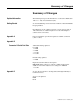
Summary of Changes Summary of Changes Updated Information The following changes to this manual have occurred since Publication 1203-5.13 – July 1998, P/N189939 (02). Getting Started Section: Establishing a Serial Connection with the 1203-CN1 Module Paragraph added: DriveExplorer (v1.01 or higher) software can now also be used on 1203-CN1s that are v2.001 or higher. Do not use DriveExplorer software with v1.xxx CN1s. Appendix A Power Consumption specification updated to 250mA at 24V DC (-20% / +30%).
Summary of Changes Notes: Publication 1203-5.
Table of Contents Preface Objectives . . . . . . . . . . . . . . . . . . . . . . . . . . . . . . . . . . . . . . . . . . . . . . . . . . . . . . . . . .P-1 Who Should Use This Manual?. . . . . . . . . . . . . . . . . . . . . . . . . . . . . . . . . . . . . . . . . .P-1 What Is the 1203-CN1 ControlNet Communications Module? . . . . . . . . . . . . . . . . . .P-1 Purpose of this Manual . . . . . . . . . . . . . . . . . . . . . . . . . . . . . . . . . . . . . . . . . . . . . . . .
ii Table of Contents Getting Started Chapter 3 Chapter Objectives . . . . . . . . . . . . . . . . . . . . . . . . . . . . . . . . . . . . . . . . . . . . . . . . . . 3-1 Factory-Default Settings for the 1203-CN1 Module’s Parameters. . . . . . . . . . . . . . . 3-1 Required Tools and Equipment . . . . . . . . . . . . . . . . . . . . . . . . . . . . . . . . . . . . . . . . . 3-2 Electrostatic Discharge Precautions . . . . . . . . . . . . . . . . . . . . . . . . . . . . . . . . . . . . .
Table of Contents Troubleshooting Chapter 7 Chapter Objectives . . . . . . . . . . . . . . . . . . . . . . . . . . . . . . . . . . . . . . . . . . . . . . . . . . LEDs on the 1203-CN1 Module. . . . . . . . . . . . . . . . . . . . . . . . . . . . . . . . . . . . . . . . . Understanding the ControlNet LEDs . . . . . . . . . . . . . . . . . . . . . . . . . . . . . . . . . . . . . Understanding the SCANport LED . . . . . . . . . . . . . . . . . . . . . . . . . . . . . . . . . . . . . .
iv Table of Contents Class Code 0x07 — Register Object. . . . . . . . . . . . . . . . . . . . . . . . . . . . . . . . . . . . D-11 Class Attributes . . . . . . . . . . . . . . . . . . . . . . . . . . . . . . . . . . . . . . . . . . . . . . . . . . D-11 Instances . . . . . . . . . . . . . . . . . . . . . . . . . . . . . . . . . . . . . . . . . . . . . . . . . . . . . . . D-11 Instance Attributes . . . . . . . . . . . . . . . . . . . . . . . . . . . . . . . . . . . . . . . . . . . . . . . .
Table of Contents v Class Code 0x99 — SCANport Pass-Through Link Object. . . . . . . . . . . . . . . . . . . D-29 Class Attributes . . . . . . . . . . . . . . . . . . . . . . . . . . . . . . . . . . . . . . . . . . . . . . . . . . D-29 Instance Attributes . . . . . . . . . . . . . . . . . . . . . . . . . . . . . . . . . . . . . . . . . . . . . . . . D-29 Common Services . . . . . . . . . . . . . . . . . . . . . . . . . . . . . . . . . . . . . . . . . . . . . . . . D-29 Object-Specific Services . . . . . .
vi Table of Contents NVS Functions. . . . . . . . . . . . . . . . . . . . . . . . . . . . . . . . . . . . . . . . . . . . . . . . . . . . . PLC Block Transfer Emulation Instruction Data . . . . . . . . . . . . . . . . . . . . . . . . . . Message Operation . . . . . . . . . . . . . . . . . . . . . . . . . . . . . . . . . . . . . . . . . . . . . . . Example. . . . . . . . . . . . . . . . . . . . . . . . . . . . . . . . . . . . . . . . . . . . . . . . . . . . . . . . Fault Command Write . . . . . . . . . . .
Preface Preface Objectives Who Should Use This Manual? Read this preface to become familiar with the rest of the manual. This preface covers the following topics: • Who should use this manual. • An overview of the 1203-CN1 ControlNet™ communications module. • The purpose of this manual. • Terms and abbreviations. • Conventions used in this manual. • Rockwell Automation support.
P-2 Preface Contents of this Manual This manual contains the following information: Chapter Publication 1203-5.13 – February, 2002 Title Contents Preface Describes the purpose, background, and scope of this manual. Also provides information on safety precautions and technical support. 1 Overview Provides an overview of the 1203-CN1 module, ControlNet, and SCANport. 2 Installation Provides procedures for installing the 1203-CN1 module.
Preface Safety Precautions Please read the following safety precautions carefully. ! ! Terms and Abbreviations P-3 ATTENTION: Only personnel familiar with SCANport devices and the associated machinery should plan or implement the installation, start-up, configuration, and subsequent maintenance of the 1203-CN1 module. Failure to comply may result in personal injury and/or equipment damage.
P-4 Preface Conventions Used in this Manual The following conventions are used throughout this manual: • Bulleted lists provide information, not procedural steps. • Numbered lists provide sequential steps or hierarchical information. • Italic type is used for chapter names and for parameter names. • Bold type is used for names of menus, menu options, screens, and dialog boxes. Important: This type of paragraph contains tips or notes that have been added to call attention to useful information.
Chapter 1 Overview Chapter Objectives Overview of the 1203-CN1 ControlNet Communications Module Chapter 1 provides an overview of your 1203-CN1 ControlNet communications module. It provides the following information: • Description of how the 1203-CN1 module works. • Overview of ControlNet. • Overview of SCANport products. • Parts of the 1203-CN1 module. • Overview of setting up the module. • Required equipment and tools.
1-2 Overview The module translates the ControlNet messages into SCANport messages that can be understood by the SCANport product. Both scheduled I/O data and unscheduled messages can be transferred through the module. ControlNet capability enhances the functionality and usefulness of the connected product and lets you communicate with the SCANport product from any node on the ControlNet network.
Overview SCANport Products 1-3 Some SCANport products support one peripheral; others support up to six peripherals. The table below lists SCANport products, the number of peripherals each supports, and the minimum and maximum I/O words allowed between the product and module.
1-4 Overview What Hardware Is Included? Figure 1.2 and the table below illustrate and list the main parts of the 1203-CN1 ControlNet communications module: Figure 1.2 Parts of the Communications Module 1 5 4 8 3 6 7 2 Number Part Description 1 DIN Rail Mount Securely attaches and electronically grounds the module to the DIN rail. 2 ControlNet Coax Connections Provide connections for ControlNet cable taps to allow either redundant or non-redundant communications over the ControlNet network.
Overview Overview of Setting Up the 1203-CN1 Module 1-5 To set up the 1203-CN1 module, you must perform the following tasks: 1. Install the module. Refer to Chapter 2, Installation. 2. If desired, configure the module’s parameters. Refer to Chapter 3, Getting Started. 3. Configure the module on the ControlNet network. Refer to Chapter 4, Configuring a Controller to Communicate with the 1203-CN1 Module.
1-6 Overview Notes: Publication 1203-5.
Chapter 2 Installation Chapter Objectives Chapter 2 provides the information that you need to install the 1203-CN1 ControlNet communications module. This information includes: • A list of tools and equipment needed for the installation. • A discussion of available cables for SCANport and ControlNet connections. • Instructions for installing the module. • Instructions for removing the module.
2-2 Installation SCANport Cables When selecting the SCANport cable to connect the module to the SCANport product, you need to: • Use an Allen-Bradley SCANport cable. Refer to the table below. Male to Male Connection➀ ➀ Male to Female Connection Length Catalog Number Length Catalog Number 1/3 m 1202-C03 1/3 m 1202-H03 1m 1202-C10 1m 1202-H10 3m 1202-C30 3m 1202-H30 9m 1202-C90 9m 1202-H90 For most installations, a male-to-male connection on the cable is required.
Installation Electrostatic Discharge Precautions 2-3 Please read the following safety precautions carefully before installing the 1203-CN1 module ! ATTENTION: The 1203-CN1 ControlNet communications module contains ESD (Electrostatic Discharge) sensitive parts. Static control precautions are required when installing, testing, or servicing this module. Device malfunction may occur if you do not follow ESD control procedures.
2-4 Installation Installing Your 1203-CN1 Module The following instructions explain how to physically install your 1203-CN1 module. Important: To guard against device malfunction, you must wear a grounding wrist strap when installing the 1203-CN1 module. 1. Set the module’s ControlNet node address by clicking the + or button to the desired value for each digit. Important: Each node on the ControlNet network must have a unique address.
Installation 2-5 3. Hook the top lip of the module’s DIN rail mount onto the top of the DIN rail and then rotate the module onto the DIN rail. You will hear the module snap into a locked position. Figure 2.2 Connecting the Module to the DIN Rail 4. Verify the module is correctly grounded to the DIN rail by using an Ohm meter to measure between: • DIN rail’s earth ground. • Metal shell in the module’s RS-232 serial port.
2-6 Installation 5. Connect the SCANport cable to the SCANport product and the module. To connect the cable to the module, align the pins on the cable with the holes in the SCANport connection and then insert the SCANport cable. The cable will click into a locked position. Figure 2.4 Connecting the SCANport Cable to the Module 6. Connect the ControlNet cable tap(s) to the ControlNet media and the module. To connect the cable tap(s) to the module, twist each onto the ControlNet Coax connection(s).
Installation 2-7 7. Connect a +24V power supply. If necessary, loosen the screw to insert the power supply connection and then re-tighten the screw. Important: You can use the two sets of holes to daisy chain the power supply between multiple 1203-CN1 modules placed close together. Figure 2.6 Connecting the Power Supply to the Module COMMON + 24 VDC The module is now physically installed. Its SCANport and ControlNet LEDs are solid green, and its Module LED is flashing green.
2-8 Installation Removing the 1203-CN1 Module If you want to remove the 1203-CN1 module, you need to: Important: To guard against device malfunction, you must wear a grounding wrist strap when removing the 1203-CN1 module. 1. Turn off the power supply to the module. 2. Disconnect all cables and the power supply from the module. Important: To disconnect the SCANport cable, gently push in the cable and then pull it out. 3.
Chapter 3 Getting Started Chapter Objectives Factory-Default Settings for the 1203-CN1 Module’s Parameters Chapter 3 provides information that you need to configure the 1203-CN1 ControlNet Communications module. This includes: • Information on the 1203-CN1 module’s default setting. • Equipment needed to make a serial connection to the module. • Instructions on how to connect a PC running terminal emulation software or a VT100-compatible terminal to the module.
3-2 Getting Started Required Tools and Equipment Electrostatic Discharge Precautions To make a serial connection to the module, you need the following: • Grounding wrist strap. • 1203-SFC serial cable. • Either a PC running a Windows terminal emulation program (e.g., HyperTerminal) or a VT100-compatible terminal. Please read the following safety precautions carefully before making a serial connection to the 1203-CN1 module.
Getting Started 3-3 Using a PC Running Terminal Emulation Software A variety of terminal emulation programs can be used to establish a serial connection to the module. The following instructions describe how to establish the initial serial connection to the module using a PC running Windows 95 HyperTerminal software. Future connections to the module can use this same configuration by clicking the icon added to the initial screen when the configuration is saved.
3-4 Getting Started 3. Double-click HyperTrm.exe. The Connection Description dialog box appears. Figure 3.3 Example Connection Dialog Box 4. Enter a name in the Name field and select any icon in the Icon field. In this example, we enter “1203-CN1” in the Name field. 5. Click OK. The Phone Number dialog box appears. Figure 3.4 Example Phone Number Dialog Box 6. In the Connect Using field, select the appropriate communications port (usually COM1 or COM2). Publication 1203-5.
Getting Started 3-5 7. Click OK. The Comm Properties dialog box appears. Figure 3.5 Example Comm Properties Dialog Box 8. Select the following settings: • 9600 in the Bits per second field. If you have previously set the module’s Serial Port Rate (Parameter 21) to enable 19200 bps, set the bps to 19200 in this field. • 8 in the Data bits field. • None in the Parity field. • 1 in the Stop bits field. • None in the Flow Control field. 9. Click OK. A blank HyperTerminal screen appears.
3-6 Getting Started 10. In the File menu, select Properties. The Properties dialog box appears. Figure 3.6 Properties Dialog Box 11. Click the Settings tab. 12. In the Function, arrow, and ctrl keys act as box, verify Terminal keys is selected. 13. In the Emulation field, verify VT100 is selected. 14. Click OK. 15. In the File menu, select Save. The configuration is saved and the icon you selected will appear in the initial HyperTerminal window next time you start HyperTerminal. Figure 3.
Getting Started 3-7 16. Press the Enter key. The main menu of the1203-CN1 ControlNet to SCANport Adapter application appears. Figure 3.8 Main Menu You now have access to the module’s software. Go to the Navigation Techniques section on page 3-8 for more information on using it. Using a VT100-Compatible Terminal Important: If you are using a PC, skip this section. The following instructions describe how to establish a serial connection to the module using a VT100-compatible terminal. 1.
3-8 Getting Started 4. Press the Enter key. The main menu of the 1203-CN1 ControlNet to SCANport Adapter application appears. Refer to the Navigation Techniques section in this chapter for information on navigating in the software. Figure 3.9 Main Menu You now have access to the module’s software. Go to the Navigation Techniques section on page 3-8 for more information on using it. Navigation Techniques To perform any of the functions in the software (e.g.
Getting Started Editing Parameters in the 1203-CN1 Module 3-9 The 1203-CN1 module has many configurable parameters. Refer to Appendix B, 1203-CN1 Module Parameters, for a detailed list. If you do not want to use the module’s default settings, edit its parameters. Important: You may also edit parameters over the ControlNet network using PCCC or emulated block transfer messages.
3-10 Getting Started 4. Edit parameters as necessary using the Left Arrow and Right Arrow keys. Refer to Navigation Techniques earlier in this chapter for information on changing values. Refer to Appendix B, 1203-CN1 Module Parameters, for valid values. 5. If necessary, reset power to the module by enabling the Reset Adapter parameter (22). Refer to Appendix B, 1203-CN1 Module Parameters, to see if the parameter you changed requires the module to be reset in order to take effect.
Getting Started 3-11 3. Scroll through the list of Event Queue parameters by pressing the Up Arrow or Down Arrow key. Number 1 2 – 33 Name Clr Event Queue Description Enable = Clears the event queue. Ready = Leaves the event queue as is. Event Queue 1 – Event Queue 32 Event in the event queue. Most recent event is listed in Event Queue 1. 4. If desired, clear the current fault in the adapter by setting Clr Event Queue (1) to Enable and pressing the Enter key.
3-12 Getting Started 3. Scroll through the list of I/O Data parameters by pressing the Up Arrow or Down Arrow key. Number Name Description 1 Logic Command Buffer for Logic Command data 2 Logic Status Buffer for Logic Status data 3 Reference Data Buffer for Reference data 4 Feedback Data Buffer for Feedback data 5 – 20 Data A1 In Val – Data D2 Out Val Data going to (Input) or coming from (Output) the SCANport device 4. Press the Escape key to return to the main menu.
Getting Started 3-13 3. Scroll through the list of DF1 statistic parameters by pressing the Up Arrow or Down Arrow key.
3-14 Getting Started Performing a Flash Upgrade to the 1203-CN1 Module To upgrade the 1203-CN1 module’s flash firmware using the module’s serial port, you need to perform a flash upgrade. Important: To perform a flash upgrade to your module’s firmware, you must use a PC running terminal emulation software. Important: To exit the flash upgrade option before the download has started, simultaneously press the Control and X keys.
Getting Started 3-15 Figure 3.14 Initial Update Flash Program Screen 4. Press Y to verify that you want to perform a flash upgrade when prompted. 5. In the Transfer menu, select Send File. The Send File dialog box appears. Figure 3.15 Send File Dialog Box 6. In the Filename field, select the file that contains the flash upgrade. Important: You can click the Browse button to locate the file that contains the flash upgrade. 7. In the Protocol field, select Xmodem. Publication 1203-5.
3-16 Getting Started 8. Click Send. A dialog box appears to report the flash is in progress. When the flash is complete, a message appears to tell you the download is complete and the module will reset itself. Figure 3.16 Message Reporting the Flash Is Complete The module resets itself, and then the Main menu appears. You must clear the drive’s fault in order to restart the drive. Publication 1203-5.
Chapter 4 Configuring a Controller to Communicate with the 1203-CN1 Module Chapter Objectives Chapter 4 provides instructions for configuring your controller to communicate with the 1203-CN1 ControlNet communications module. This allows the product connected to the 1203-CN1 module to be an active node on the ControlNet network. This chapter provides information on: • RSNetWorx. • Equipment and software needed for the configuration. • Configuring a controller to communicate with the 1203-CN1 module.
4-2 Configuring a Controller to Communicate with the 1203-CN1 Module Configuring a Controller to Communicate with the 1203-CN1 Module For the controller on the ControlNet network to transmit control I/O and/or messages to the 1203-CN1 module, you must configure it to recognize and communicate with the 1203-CN1 module. These instructions describe how to use RSNetWorx to configure a new ControlNet network in online mode. The main steps in the configuration are: • Using online mode in RSNetWorx.
Configuring a Controller to Communicate with the 1203-CN1 Module 4-3 2. Click the Online box. RSLinx starts in the background to provide a communications interface and then the Browse for Network dialog box appears. Figure 4.2 Example Browse for Network Dialog Box 3. If available, click the Autobrowse box. 4. If necessary, click the plus sign to view the available networks. Figure 4.3 Example Browse for Network Dialog Box with Available Networks Displayed Publication 1203-5.
4-4 Configuring a Controller to Communicate with the 1203-CN1 Module 5. Select your ControlNet network and click OK. A graphical representation of your network appears. Figure 4.4 Example Network Displayed in RSNetWorx Important: Note the following about our example: Publication 1203-5.13 – February, 2002 • In Figure 4.4, Node 1 is the controller (PLC-5), Node 4 is the SCANport product to which the 1203-CN1 module is connected, and Node 20 is the PC we are using to configure the network.
Configuring a Controller to Communicate with the 1203-CN1 Module 4-5 6. In the Network menu, select Actions and then Configurations List. The ControlNet Configuration dialog box appears. Figure 4.5 Example ControlNet Configuration Dialog Box 7. Identify the device(s) that need(s) to be mapped to the network. The Current Configuration list (blank in Figure 4.5) shows the devices configured on the ControlNet network. The Network Configuration list shows devices on the network.
4-6 Configuring a Controller to Communicate with the 1203-CN1 Module Mapping the 1203-CN1 Module to the ControlNet Network You must configure the 1203-CN1 module on the ControlNet network so that the controller can communicate with it. Follow these instructions: 1. Click the Edits Enabled box. Important: If the Online/Offline Mismatch dialog box appears, click OK to use the online data. If prompted to save, save the data. 2. Right-click on the controller’s icon (PLC-5) and select ControlNet Configuration.
Configuring a Controller to Communicate with the 1203-CN1 Module 4-7 3. Select the line with the SCANport product you want to configure. Important: You can verify that you’ve selected the correct line by making sure it has the same node number that you set for the module during the installation. 4. In the Insert menu, select Device Connection. Figure 4.7 Example of the Product Line after Drive Connection Is Selected 5.
4-8 Configuring a Controller to Communicate with the 1203-CN1 Module 7. Double-click the Input Size field in your product’s row and select the appropriate size. Valid sizes are 2, 4, 6, 8, and 10. To determine the size, add 2 if Control I/O is enabled and add 2 for each datalink that is enabled. For example, if Control I/O data and all datalinks are enabled, the size would be 10. 8. Double-click the Output Size field in your product’s row and select the appropriate size.
Configuring a Controller to Communicate with the 1203-CN1 Module 4-9 10. In the Configuration menu, select Auto Map and then All Entries. Addresses are put in the Input Address and Output Address columns. Figure 4.9 Example Configuration Important: If you want to map the addresses manually, click in the correct field and then enter the address. Make sure you insert a valid address. Refer to the online help for information on manually mapping an address. Publication 1203-5.
4-10 Configuring a Controller to Communicate with the 1203-CN1 Module 11. In the Network menu, select Save. The Save Configuration dialog box appears. Figure 4.10 Save Configuration Dialog Box 12. Click OK. The Save As dialog box may appear. Important: If the ControlNet Services dialog box appears with a warning about the MAX scheduled node being set too low, click OK. You will correct the problem later while verifying network properties. Figure 4.11 Save As Dialog Box 13.
Configuring a Controller to Communicate with the 1203-CN1 Module 4-11 14. In the Network menu, select Exit. The ControlNet Configuration screen closes and the RSNetWorx screen reappears. Figure 4.12 Example RSNetWorx Screen with Configured Network Important: The icon for the SCANport product connected to the 1203-CN1 module (node 4 in Figure 4.12) should appear with a gray flag on it to indicate it is configured.
4-12 Configuring a Controller to Communicate with the 1203-CN1 Module 15. In the Network menu, select Action and then Configuration List. The ControlNet Configuration dialog box appears. Figure 4.13 Example ControlNet Configuration Dialog Box 16. Verify all devices are configured on your network. Devices configured on the network will appear in the Current Configuration list. Figure 4.13 shows all devices are configured on our example network. 17. Click OK to close the dialog box.
Configuring a Controller to Communicate with the 1203-CN1 Module 4-13 Verifying Network Properties For your network to function properly, you must set the correct properties. To verify that the correct properties are set, follow these instructions: 1. Click the Edits Enabled box. 2. In the Network menu, select Properties. The Network Properties: ControlNet dialog box appears. Figure 4.14 Network Parameters Tab of the Network Properties: ControlNet Dialog Box 3.
4-14 Configuring a Controller to Communicate with the 1203-CN1 Module 4. If a special media configuration is required (e.g., repeater), select the Media Configuration tab and make the appropriate changes. Refer to the online help for more information. Figure 4.15 Media Configuration Tab 5. If desired, select the General tab and enter a name and description for the network. Figure 4.16 Example General Tab Publication 1203-5.
Configuring a Controller to Communicate with the 1203-CN1 Module 4-15 6. Click OK. 7. In the Network menu, select Save to save the properties and download them to the PLC. The module is now mapped on the network and the controller will communicate with it. If all mapped devices are present and operational: • I/O and ControlNet Channel LEDs on the controller will be solid green. • ControlNet LED(s) on the 1203-CN1 will be solid green.
4-16 Configuring a Controller to Communicate with the 1203-CN1 Module Notes: Publication 1203-5.
Chapter 5 PLC Ladder Logic Programming Chapter Objectives Chapter 5 provides information needed to create the PLC Ladder Logic program that the controller will use to transmit control I/O and messages to and from the SCANport product. This information includes: • Discussion of PLC ladder logic programs. • Equipment and software needed to create a PLC Ladder Logic program. • Example PLC ladder logic program to control the drive.
5-2 PLC Ladder Logic Programming What Are PLC Ladder Logic Programs? A PLC ladder logic program lets you control the drive and the messaging from the PLC to the drive. Figure 5.1 shows how the I/O image table for the controller (e.g., PLC) relates to the 1336 PLUS drive when a 1203-CN1 module is used. Figure 5.
PLC Ladder Logic Programming Required Equipment and Software 5-3 Before creating a PLC ladder logic program, your PC should be: Example Ladder Logic Program • Running RSLogix5 and RSLinx applications. Refer to http://www.software.rockwell.com for more information on these products. • Connected to and communicating with the ControlNet network using a 1784-KTCX card, 1784-PCC card or 1770-KFC adapter. The following is an example ladder logic program for a 1305 drive or a 1336 PLUS drive.
5-4 PLC Ladder Logic Programming The 1305 or 1336 PLUS drive in this example sends the following Logic Status Data to the PLC.
PLC Ladder Logic Programming 5-5 The portion of the program shown in Figure 5.2 controls the starting and stopping of the drive. When the start button is pushed, the drive will start. When the stop button is pushed, the drive will stop. Figure 5.
5-6 PLC Ladder Logic Programming The portion of the program shown in Figure 5.4 displays the status of the drive by reading the status information in the drive’s logic status word and displaying it at the operator’s station. Figure 5.
Chapter 6 Using Messages Chapter Objectives Chapter 6 provides information about using messages on the ControlNet network. It includes the following: • Required equipment and software. • Discussion of messaging. • Examples of rungs that enable messaging. This chapter assumes you already have experience creating ladder logic programs and using messages in RSLogix5.
6-2 Using Messages The following must be completed in the Target Device section: • In the Data Table Address field, enter the starting address of the source or the destination file in the 1203-CN1 module. Refer to Appendix C, N-File Structure, to see what data is contained in each N-file. • In the ControlNet Path field, enter the node address for the 1203-CN1 module. Important: For more information, refer to the RSLogix5 online help. 4.
Using Messages 6-3 Important: If you refer to Appendix C, N-File Structure, you will find that SCANport product parameter values are contained in the N10:1 – N12:999. Important: To view the 1203-CN1 module’s parameters, you would specify N13:1 instead of N10:1. Figure 6.2 Read Parameters Logic. Figure 6.3 contains the values read by this example rung. The zero element contains the value of parameter 1, the one element contains the value of parameter 2, etc. Figure 6.
6-4 Using Messages Example PLC-5 Typed Read of All Information about a Parameter Figure 6.4 contains an example of a PCCC message. This message allows the PLC to read all information about parameter 1 in the drive. Figure 6.4 Example Full Read Rung Read All Information available about Parameter Number 1 User Input I:000 MSG Read/Write Message Control MG15:1 Setup Screen 0001 16 EN DN ER In the MSG dialog box (Figure 6.5), the configuration for the message is specified.
Using Messages 6-5 Figure 6.6 and Figure 6.7 display the same results in ASCII and decimal text, respectively. Figure 6.6 Example Results in ASCII Text Important: In Figure 6.6, elements 6 – 12 spell out “Output Voltage.” The text in each bit is reversed (e.g., element 6 is “uO” instead of “Ou”) because of the method used to display ASCII text in an N-file. Figure 6.7 Example Results in Decimal Code Publication 1203-5.
6-6 Using Messages Example Fault Queue Read Emulated Block Transfer Figure 6.8 contains an example of an emulated block transfer. In emulated block transfers, the first rung always writes the data from the drive to the N:40 file in the module; the second rung then reads the data from this file. Important: You can activate only one emulated block transfer message at a time. If more than one message is active, data may be processed out of order and inaccurate results may be supplied. Figure 6.
Using Messages 6-7 Figure 6.9 MG15:1 Message Control Block Setup The MSG dialog box in Figure 6.10 specifies the configuration for the Read Response message. • In the Data Table Address field in the This PLC-5 section, N23:0 is specified. This is where the results will be reported. • In the Size in Elements field in the This PLC-5 section, 20 is specified. The response will be 20 elements. • In the Data Table Address field in the Target Device section, N40:0 is specified.
6-8 Using Messages Figure 6.11 shows the results of the typed write command. Figure 6.11 Example Results of the Typed Write Figure 6.12 and Figure 6.13 display the same results of the typed read command in ASCII and decimal text, respectively. Figure 6.12 Example Results in ASCII Text Important: In Figure 6.12, elements 3 – 8 spell out “Serial Fault.” The text in each element is reversed (e.g., element 3 is “eS” instead of “Se”) because of the method used to display ASCII text in an N-file. Figure 6.
Chapter 7 Troubleshooting Chapter Objectives LEDs on the 1203-CN1 Module Chapter 7 provides information about the LEDs and basic troubleshooting procedures. This chapter covers the following topics: • Locating the LEDs. • Using the LEDs to troubleshoot. Your 1203-CN1 module has four LED status indicators. The LEDs provide status information about ControlNet channel(s), SCANport, and the module itself. Refer to Figure 7.1. Figure 7.
7-2 Troubleshooting Understanding the ControlNet LEDs LEDs Viewed: ControlNet A and B Together ControlNet A or B Independently If: When viewing the ControlNet LEDs, the color and status (solid or flashing) of the LEDs are significant. In addition, the ControlNet Channel A and Channel B LEDs may need to be viewed together or independently, depending on their state. Refer to this table. Cause: Action: Both LEDs are off. A reset has occurred or there is no power. Apply power to the module.
Troubleshooting Understanding the SCANport LED LEDs Viewed: SCANport If: 7-3 When viewing the SCANport LED, the color and status (solid or flashing) of the LED are significant. Refer to this table. Cause: Action: Solid red Either the SCANport interface is not connected to a SCANport product, or it is connected but for some reason has not detected a valid SCANport ID. 1. Verify the SCANport product is powered. 2. Check media for broken cables, loose connectors, etc.
7-4 Troubleshooting Understanding the Module LED LEDs Viewed: Module When viewing the Module LED, the color, status (solid or flashing), and flash pattern (number of flashes before a pause) are significant. Refer to this table. If: Cause: Action: Off The adapter is not receiving power. Solid red The hardware or firmware is bad. Flashing red (1 flash) A flash update is in progress or the firmware has detected an error. Flashing red (2 flashes) RAM test failed. 1.
Appendix A Specifications Appendix Objectives Appendix A provides the specifications that you may need to install, repair, or use your 1203-CN1 ControlNet communications module. Specifications The following table gives the specifications for the 1203-CN1 ControlNet communications module. Category Specifications Dimensions 3.92 x 2.69 x 3.54 in (99.5 x 68.4 x 90.0 mm) Weight 0.52 lbs. (236.
A-2 Specifications Notes: Publication 1203-5.
Appendix B 1203-CN1 Module Parameters Appendix Objectives What Are Datalinks? Appendix B provides information on the 1203-CN1 SCANport to ControlNet module’s parameters. The information includes: • Discussion of datalinks. • Discussion of Fault Configurable inputs. • List of parameters. Datalinks let you increase the scheduled I/O values to and from a SCANport device (provided the SCANport device supports datalinks).
B-2 1203-CN1 Module Parameters controlled devices that depend on pre-programmed output from the module. ATTENTION: Risk of severe bodily injury or loss of life exists. The Idle Flt Action (9) and Comm Flt Action (10) parameters allow the user to change the default configuration that would allow the module and associated drive to continue to operate if communication is lost.
1203-CN1 Module Parameters Default Writable Reset or Power Cycle to Take Effect 0 = Disabled 1 = Enabled 0=Disabled Yes Yes Determines whether to pass control data contained in datalink C from a ControlNet connection to the SCANport product. DataLnk D Config 0 = Disabled 1 = Enabled 0=Disabled Yes Yes Determines whether to pass control data contained in datalink D from a ControlNet connection to the SCANport product.
B-4 1203-CN1 Module Parameters # Name Valid Values/ Settings Default Writable Reset or Power Cycle to Take Effect 16 Fault Cfg B2 In 0 – 65535 0 Yes No Provides the second word of datalink B data to the SCANport product when the module is instructed to use the values for the Fault Cfg parameters. 17 Fault Cfg C1 In 0 – 65535 0 Yes No Provides the first word of datalink C data to the SCANport product when the adapter is instructed to use the values for the Fault Cfg parameters.
Appendix C N-File Structure Appendix Objectives Appendix C details the N-file structure in the 1203-CN1 module. The N-files contain data for the 1203-CN1 module and the connected SCANport product. If you need to access information in the product using messages or program a PLC or PC, you will need to know what data is stored in each N-file. N-File Structure The following table lists the N-files and a description of each N-file’s content.
C-2 N-File Structure N-File N50:1 – N50:249 N51:0 – N51:249 N52:0 – N52:249 N53:0 – N53:249 N54:0 – N54:249 N55:0 – N55:249 N56:0 – N56:249 N57:0 – N57:249 N58:0 – N58:249 N59:0 – N59:249 N60:0 – N60:249 N61:0 – N61:249 SCANport Product Parameter Value Read/Write (Parameters 1 – 2999) N90:1 – N90:249 N91:0 – N91:249 N92:0 – N92:249 N93:0 – N93:249 N94:0 – N94:249 N95:0 – N95:249 N96:0 – N96:249 N97:0 – N97:249 N98:0 – N98:249 N99:0 – N99:249 N100:0 – N100:249 N101:0 – N101:249 SCANport Product Parameter
Appendix D ControlNet Objects Appendix Objectives Appendix D defines the ControlNet object classes, class services, and attributes that are supported by the 1203-CN1 ControlNet communications module. These objects can be used to develop programs for the module. This appendix assumes that you have experience in object programming. Object Classes The 1203-CN1 module supports the following object classes.
D-2 ControlNet Objects: Class Code 0x01 — Identity Object Class Code 0x01 — Identity Object The identity object provides identification and general information about the device. Class Attributes Attribute ID Access Rule 1 Name Data Type Description Get Revision UINT Revision of this object. First revision, value=1. Get Max Instance UINT Maximum instance number of an object currently created in this class level of the device.
ControlNet Objects: Class Code 0x01 — Identity Object D-3 Instance Attributes Attribute ID 1 Access Rule Name Data Type Get Vendor ID UINT Identification of each vendor by number. 1 = Allen-Bradley Get Device Type UINT Indication of general type of product. 0x69 = Sub-Component 0x6E = SCANport Device Get Product Code UINT Identification of a particular product of an individual vendor. 0x0002 = 1336 PLUS 0.5 – 10 HP 0x0003 = 1336 PLUS 7.
D-4 ControlNet Objects: Class Code 0x01 — Identity Object Get_Attribute_All Response At the Class level the order of the attributes returned in the “Object/ service specific reply data” portion of the Get_Attribute_All response is defined as follows: Attribute ID Definition 1 Revision (low BYTE) Default = 1. Revision (high BYTE) Default = 0. 2 Max Instance (low BYTE) Default = 1. Max Instance (high BYTE) Default = 0. 6 Max ID Number of Class Attributes (low BYTE) Default = 0.
ControlNet Objects: Class Code 0x02 — Message Router Object Class Code 0x02 — Message Router Object D-5 The Message Router Object provides a messaging connection point through which a client may address to any object class or instance residing in the physical devices. Class Attributes Attribute ID 1 Access Rule Name Data Type Get Revision Get Optional Attribute List STRUCT of Number Attributes UINT Optional Attributes ARRAY of UINT List of optional attribute numbers.
D-6 ControlNet Objects: Class Code 0x02 — Message Router Object Instance Attributes Attribute ID Access Rule Get 1 2 Name Object_List Data Type Description STRUCT of A list of supported objects. Structure with an array of object class codes supported by the device via the message router. Number UINT Classes ARRAY of UINT Number of supported classes in the classes array. List of supported class codes. Get Number available UINT Maximum number of connections supported.
ControlNet Objects: Class Code 0x04 — Assembly Object Class Code 0x04 — Assembly Object D-7 The Assembly Object binds attributes of multiple objects, allowing data to or from each object to be sent or received over a single connection. Assembly objects are used to produce and/or consume data to/from the network. An instance of the assembly object can both produce and consume data from the network if designed to do so.
D-8 ControlNet Objects: Class Code 0x04 — Assembly Object Common Services Implemented for: Service Code 0x0E Publication 1203-5.
ControlNet Objects: Class Code 0x06 — Connection Manager Object Class Code 0x06 — Connection Manager Object D-9 The Connection Manager Object is used to manage the establishment and maintenance of communication connections. Class Attributes Attribute ID 1 Access Rule Name Data Type Description Get Revision UINT Revision of this object. First revision, value=1. Set Max Instance UINT Maximum instance number of an object currently created in this class level of the device.
D-10 ControlNet Objects: Class Code 0x06 — Connection Manager Object Attribute ID Access Rule Get Name Data Type Connection Entry List STRUCT of NumConnEntries UINT Number of Conn Array Entries (bit field). This attribute, divided by 8 and incremented for any remainder, gives the length of the array in the Conn Open Bits field. ConnOpenBits ARRAY of BYTE List of connection data which may be individually queried by the Get/Search Connection Data Services.
ControlNet Objects: Class Code 0x07 — Register Object Class Code 0x07 — Register Object D-11 The Register Object is used to address individual bits or a range of bits. It may operate as either a producer (input) register or a consumer (output) register. A producer register object produces data onto the network. A consumer register object consumes data from the network. Message writes to the Register Object can perform control functions.
D-12 ControlNet Objects: Class Code 0x07 — Register Object Instance Attributes Setting of an assembly attribute can only be accomplished through a connection. This feature is to prevent accidental control of the SCANport product. Attribute ID Access Rule Name Data Type Description Get Bad Flag BOOL If set to 1, then attribute 4 may contain invalid, bad or otherwise corrupt data.
ControlNet Objects: Class Code 0x0F — Parameter Object Class Code 0x0F — Parameter Object D-13 The Parameter Object provides a known, public interface for device configuration data. This object also provides all the information necessary to define and describe each individual configuration parameter of a device. Class Attributes Attribute ID 1 Access Rule Name Data Type Get Revision UINT Revision of this object. First revision, value=1.
D-14 ControlNet Objects: Class Code 0x0F — Parameter Object Instance Attributes Attribute ID Access Rule Stub/Full Name ➀ Stub Parameter Value Set Stub Link Path Size Set Stub Link Path 1 Data Type Specified in Actual value of parameter. Data type Descriptor, specified in descriptor, data type, and Data Type and data size.➀ ➁ Data Size attributes. USINT 2 3 Description Size of Link Path attribute. If this attribute is 0, then no link is specified. Number of BYTEs in attribute 3.
ControlNet Objects: Class Code 0x0F — Parameter Object Attribute ID Access Rule Stub/Full 16 Get Full Scaling Offset UINT Offset for scaling formula. Get Full Multiplier Link UINT Parameter object instance number of multiplier source. Get Full Divisor Link UINT Parameter object instance number of base source. Get Full Base Link UINT Parameter object instance number of offset source. Get Full Offset Link UINT Parameter object instance number of offset source.
D-16 ControlNet Objects: Class Code 0x0F — Parameter Object Data Types for Instance Attribute 5 Attribute ID Value Publication 1203-5.
ControlNet Objects: Class Code 0x0F — Parameter Object D-17 Common Services Implemented for: Service Code Service Name Class Instance 0x01 Yes Yes Get_Attribute_All 0x0E Yes Yes Get_Attribute_Single 0x10 Yes Yes Set_Attribute_Single Get_Attribute_All Response At the class level, the order of the attributes returned in the “object/ services specific reply data” portion of the Get_Attribute_All response is as follows: Class Attribute ID Definition Revision (low BYTE) Default = 1 1 Revision
D-18 ControlNet Objects: Class Code 0x0F — Parameter Object Class Attribute ID Attribute Name and default Value 14 Scaling Divisor Default = 1 15 Scaling Base Default = 1 16 Scaling Offset Default = 0 17 Multiplier Link Default = 0 18 Divisor Link Default = 0 19 Base Link Default = 0 20 Offset Link Default = 0 21 Decimal Precision Default = 0 Object Specific Services Implemented for: Service Code 0x4B Service Name Class Instance No Yes Get_Enum_String Enumerated strings are human-re
ControlNet Objects: Class Code 0x10 — Parameter Group Object Class Code 0x10 — Parameter Group Object D-19 The Parameter Group Object identifies and provides access to groups of parameters in a device grouping. The Parameter Group Object provides convenient access to related sets of parameters. Class Attributes Attribute ID 1 Access Rule Name Data Type Description Get Revision UINT Revision of this object. First revision, value=1.
D-20 ControlNet Objects: Class Code 0x10 — Parameter Group Object Common Services Implemented for: Service Code Service Name Class Instance 0x01 Yes Yes Get_Attribute_All 0x10 Yes No Set_Attribute_Single 0x0E Yes Yes Get_Attribute_Single Get_Attribute_All Response At the class level, the order of the attributes returned in the “object/ service specific reply data” portion of the Get_Attribute_All response is as follows: Class Attribute ID Definition 0 Revision (low BYTE) Default = 1 1
ControlNet Objects: Class Code 0xF0 — ControlNet Object Class Code 0xF0 — ControlNet Object D-21 The ControlNet Object provides a consistent Station Management interface to the Physical and Data Link Layers. This object makes diagnostic information from these layers available to client applications. Class Attributes Attribute ID Access Rule Name 0x01 Get Revision 0x02 Get Max Instance Data Type UINT UDINT Description Revision of this object. First revision, value=1. Maximum instance number.
D-22 ControlNet Objects: Class Code 0xF0 — ControlNet Object Attribute ID Access Rule Name Get/Get_and_ NUT_overloads Clear (continued) slot_overloads 0x82 (continued) Description USINT No unscheduled time in NUT (all time used for scheduled transmissions). USINT More scheduled data queued for one NUT than allowed by sched_max_frame parameter. blockages USINT Single Lpacket size exceeds sched_max_frame parameter.
ControlNet Objects: Class Code 0xF0 — ControlNet Object Attribute ID Access Rule Get Name Data Type Error_log 0x86 D-23 Description STRUCT of 10 Driver firmware buffer error counts and BYTEs troublesome node list. Buffer_errors Error_log UINT Buffer event counter. BYTE [8] Bad MAC frame log.
D-24 ControlNet Objects: Class Code 0xA1 — Non-Volatile Storage Object Class Code 0xA1 — Non-Volatile Storage Object The Non-Volatile Storage (NVS) Object stores information during the loss of power to a module. The object is an abstraction of EEPROM, FLASH EPROM, and Battery Backed RAM. Class Attributes Attribute ID Access Rule Name Data Type Description UINT Revision of this object. (Important: All class definitions are required to include this class attribute.) Value is 02.
ControlNet Objects: Class Code 0xA1 — Non-Volatile Storage Object D-25 Instance Attributes Attribute ID Access Rule 1 Get Status UINT Current status of the NVS object. Get Major Instance Revision USINT Current Major Revision number of this NVS instance. Start at 1. Minor Instance Revision USINT Current Minor Revision number of this NVS instance. Start at 1. 2 Name Data Type Description ➀ The Status attribute reports the current status based upon the state of an instance of the object.
D-26 ControlNet Objects: Class Code 0x93 — SCANport Pass-Through Parameter Object Class Code 0x93 — SCANport Pass-Through Parameter Object The SCANport Pass-Through Parameter Object lets you perform a scattered read or write.
ControlNet Objects: Class Code 0x97 — SCANport Pass-Through Fault Object Class Code 0x97 — SCANport Pass-Through Fault Object D-27 The SCANport Pass-Through Fault Object provides information on the product’s fault queue. Class Attributes Attribute ID Access Rule 2 Data Type Description Set Write Fault Command BYTE 1 = Clear Faults 2 = Clear Fault Queue 3 = Reset Product Get Read Number of Fault Queue Entries BYTE Reads the number of fault queue entries.
D-28 ControlNet Objects: Class Code 0x98 — SCANport Pass-Through Warning Object Class Code 0x98 — SCANport Pass-Through Warning Object The SCANport Pass-Through Warning Object provides information on the product’s warning queue. Class Attributes Attribute ID Access Rule Name Data Type 0 Set Write Warning Command BYTE 1 Set Read Number of Warning Queue Entries BYTE Description Write Warning Command.
ControlNet Objects: Class Code 0x99 — SCANport Pass-Through Link Object Class Code 0x99 — SCANport Pass-Through Link Object D-29 The SCANport Pass-Through Link Object lets you perform a scattered read or write of a number of links or a single read or write of a link. Class Attributes Attribute ID Access Rule Name Data Type Description 0 Set Link Command BYTE 1 = Clear all links. 1 Get NVS Link Diagnostic Value WORD Checksum.
D-30 ControlNet Objects: Class Code 0x67 — PCCC Object Class Code 0x67 — PCCC Object The PCCC Object is used to process encapsulated PCCC messages from ControlNet. The PCCC Object does not implement any specific class or instance attributes, so the instance field for any received messages is ignored.
Appendix E Supported PCCC Messages Appendix Objectives Appendix E lists PCCC messages and whether they are supported by the 1203-CN1 ControlNet Communications Module. This information is provided for those writing software to perform monitoring and configuration functions from a PC. Supported PCCC Messages The following table lists PCCC messages and whether each message is supported.
E-2 Supported PCCC Messages PCCC Error Response Codes The following table lists the PCCC error response codes. Messages Related documentation Publication 1203-5.13 – February, 2002 STS EXT STS Problem 0x10 Illegal command or format. The adapter does not support this command. All Messages 0x30 Remote station host is not present, disconnected, or shutdown. The SCANport product is disconnected or cannot communicate for some other reason. 0xF0 0x01 Illegal Address Format.
Appendix F Supported Emulated Block Transfer Commands Appendix Objectives Appendix F provides information about supported emulated block transfer commands. You may want to use these to set or obtain information about parameters in the SCANport product connected to the 1203-CN1. This appendix contains the following: • List of supported emulated block transfer commands. • Description of the emulated block transfer status word.
F-2 Supported Emulated Block Transfer Commands: Emulated Block Transfer Status Word Emulated Block Transfer Status Word When an operation is unsuccessful, header word 2 of the drive response contains a negative value (bit 15 = 1). If an error occurs, the drive also returns a status word to indicate the reason for the failure. The location of the status word is typically header word 3 in the drive response, but will depend on the message.
Supported Emulated Block Transfer Commands: Parameter Value Read Parameter Value Read F-3 Parameter Value Read reads the 16-bit parameter data value for the selected parameter number.
F-4 Supported Emulated Block Transfer Commands: Parameter Value Write Parameter Value Write Parameter Value Write writes a 16-bit parameter data value to the selected parameter number.
Supported Emulated Block Transfer Commands: Parameter Read Full Parameter Read Full F-5 Parameter Read Full provides all known attributes for the parameters requested. This information includes the parameter’s current value, descriptor, multiply and divide value, base value, offset value, text string, group element reference, minimum value, maximum value, default value, and unit text string.
F-6 Supported Emulated Block Transfer Commands: Parameter Read Full Message Structure (Continued) Drive Response File, Group, Element Data Word 17 Minimum Value Data Word 18 Maximum Value Data Word 19 Default Value Char 2 Char 1 Char 4 Char 3 Unit Text Data Word 20 Data Word 21 Data Word 22 Message Operation Parameter Read Full retrieves the attributes of the specified parameter. The attributes for each parameter include the data, minimum and maximum values, and the parameter text.
Supported Emulated Block Transfer Commands: Parameter Read Full F-7 This example shows the response message in both binary and ASCII. Note the ASCII information beginning with word 9. The parameter name characters return in reverse order for each word. Word 9 has the ASCII value of (aM). To read this, reverse the word to read (Ma). The next word (ix), reversed, gives you (xi). These words, along with the following two words, form the word Maximum.
F-8 Supported Emulated Block Transfer Commands: Product ID Number Read Product ID Number Read Product ID Number Read returns the product ID of the device to which the 1203-CN1 module is connected.
Supported Emulated Block Transfer Commands: Product ID Number Read F-9 Message Operation Product ID Number Read, through the drive response message word 3, indicates the type of device the 1203-CN1 module is connected to. This value is defined in the message response chart shown above. If an error has occurred, word 1 of the response returns a negative value of -32512. Example In this example, the Product ID Number Read was requested.
F-10 Supported Emulated Block Transfer Commands: Scattered Parameter Value Read Scattered Parameter Value Read Scattered Parameter Value Read reads a scattered list of parameters.
Supported Emulated Block Transfer Commands: Scattered Parameter Value Read F-11 Message Operation Scattered Parameter Value Read reads a pre-defined group of parameter values, in any order, from the device. You define the number of parameters to read in word 2 of the request. The parameters to be read and their order are defined starting with word 3. An unused word is left between each parameter request, so the drive can respond with the parameter value, as shown.
F-12 Supported Emulated Block Transfer Commands: Scattered Parameter Value Write Scattered Parameter Value Write Scattered Parameter Value Write writes to a scattered list of parameters and returns the status of each parameter. If any of the states have errors, the parameter number is negative.
Supported Emulated Block Transfer Commands: Scattered Parameter Value Write F-13 Message Operation Scattered Parameter Value Write writes data values to a predefined group of device parameters in any order. You define the number of parameters to write in word 2. The parameters to be written to and their order are defined starting with word 3. If an error occurs while writing to any of the parameters: • Word 1 of the drive response returns a value of -32765.
F-14 Supported Emulated Block Transfer Commands: NVS Functions NVS Functions NVS (Non-Volatile Storage) Functions activates an NVS function.
Supported Emulated Block Transfer Commands: Fault Command Write Fault Command Write F-15 Fault Command Write activates the Clear Fault, Clear Fault Queue, and Drive Reset functions.
F-16 Supported Emulated Block Transfer Commands: Fault Queue Entry Read Full Fault Queue Entry Read Full Fault Queue Entry Read Full reads the contents of the specified fault queue entry. A message is returned which includes the fault text and fault code associated with the specified fault queue entry. The 1336 FORCE drive also returns the time stamp associated with the fault.
Supported Emulated Block Transfer Commands: Fault Queue Entry Read Full F-17 Message Operation Fault Queue Entry Read Full reads the contents of the fault queue specified in word 3 of the request. The response returns the fault text which can be ASCII text. Every two characters of text are in reverse order. Also, the 1336 FORCE drive returns a time stamp, indicating the day and time the fault occurred. If an error has occurred, word 1 of the response returns a negative value.
F-18 Supported Emulated Block Transfer Commands: Fault Queue Size Fault Queue Size Fault Queue Size gets the number of fault entries allowed in the fault queue.
Supported Emulated Block Transfer Commands: Trip Fault Queue Number Trip Fault Queue Number F-19 Trip Fault Queue Number provides the fault queue number of the fault that caused the device to trip.
F-20 Supported Emulated Block Transfer Commands: Trip Fault Queue Number Notes: Publication 1203-5.
Index Numerics 1203-CN1 module configuring to communicate with a controller, 4-1 to 4-15 definition, P-1 editing parameters, 3-9 event queue, 3-10 firmware, 3-14 flash upgrade, 3-14 function, 1-1 hardware, 1-4 icon in RSNetWorx, 4-4 illustration, 1-4 installation, 2-1 to 2-8 LEDs, 7-1 to 7-4 mapping to the ControlNet network, 4-6 to 4-12 network node address, 1-4, 2-4, 4-4 parameters, 3-1, 3-9, B-2 to B-4 power supply, 2-7 removal, 2-8 resetting, B-4 serial connection to, 3-2 serial number, 3-13 setting up
I–2 Index ControlNet objects, D-1 to D-30 assembly, D-7 connection manager, D-9 ControlNet, D-21 identity, D-2 message router, D-5 non-volatile storage, D-24 parameter, D-13 parameter group, D-19 PCCC, D-30 register, D-11 SCANport pass-through, D-26 SCANport pass-through fault, D-27 SCANport pass-through link, D-29 SCANport pass-through warning, D-28 equipment required, 1-5 configuring a controller, 4-1 installation, 2-1 ladder logic programming, 5-3, 6-1 serial connection, 3-2 event queue, 3-10 F fault
Index messaging description, 6-1 emulated block transfer, 6-6, F-1 to F-19 examples, 6-2 to 6-8 N-file structure, 6-3, C-1 PCCC, 6-1 to 6-8, E-1 to E-2 module, refer to 1203-CN1 module N navigation techniques in software, 3-8 network node address highest on network, 4-13 highest receiving I/O data, 4-13 setting on 1203-CN1 module, 2-4 viewing in RSNetWorx, 4-4 N-file structure, 6-3, C-1 I–3 R removal of 1203-CN1 module, 2-8 resetting the module, B-4 RSLinx, 4-3 RSLogix5 description, 5-2 RSNetWorx descrip
I–4 Index Notes: Publication 1203-5.
Notes
Notes
Notes
Notes
Notes
Notes
We Want Our Manuals to be the Best! You can help! Our manuals must meet the needs of you, the user. This is your opportunity to make sure they do just that. By filling out this form you can help us provide the most useful, thorough, and accurate manuals available. Please take a few minutes to tell us what you think - then mail this form or FAX it.
FOLD HERE FOLD HERE NO POSTAGE NECESSARY IF MAILED IN THE UNITED STATES BUSINESS REPLY MAIL FIRST CLASS PERMIT NO. 413 MEQUON, WI POSTAGE WILL BE PAID BY ADDRESSEE ALLEN-BRADLEY Attn: Marketing Communications P.O.
1336 FORCE, 1336 IMPACT, SCANport RSLinx, RSNetWorx, and RSLogix5 are trademarks of Rockwell International, Inc. PLC and PLC-5 are registered trademarks of Rockwell International, Inc. ControlNet is a trademark of ControlNet International. Windows and Microsoft are either registered trademarks or trademarks of Microsoft Corporation.
Publication 1203-5.13 February, – 2002 Supercedes 1203-5.13– July, 1998 P/N 189939-P02 Copyright (C) 2001 Rockwell Automation. All rights reserved. Printed in USA.