
Instruction Manual

Publication 1202-IN001B-EN-P – May 2004 P/N 319926-P02
Supersedes 1202-IN001A-EN-P, September 2003 Copyright © 2004 Rockwell Automation. All rights reserved. Printed in China.
Cable Connections
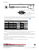
1. At one end of the connecting cable, strip back the cable jacket 30 mm (1.18 in.) to expose the shield and twisted wire pairs. Then strip
back the cable’s shield 24 mm (0.94 in.) to expose the twisted wire pairs. Remove 4 mm (0.16 in.) of insulation from the wires of each
twisted pair. Then connect the stripped wires of each twisted pair to their corresponding terminals shown in Table 1
:
Important: Cable wire colors are subject to change at any time. If the connecting cable wire colors are different than those listed above,
make sure that each twisted pair is terminated to the same terminal numbers on both ends of the cable.
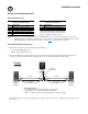
2. Make sure that the connecting cable’s shield is tightly secured under the cable shield clamp (A). If a foil shield is used (Quabbin cable),
the blue side of the foil shield is non-conductive. In this case, fold back the foil to expose the silver side of the foil to the shield clamp
before installing.
3. Tightly secure the connecting cable’s outer jacket under the cable strain relief clamp (B).
4. The terminal adapter’s two mounting holes (C) can be used to secure the adapter to a flat surface. Use #8 screws (not supplied) of an
appropriate length for the application.
5. Connect the other end of the connecting cable to the second terminal adapter. Repeat steps 1 through 4.
Table 1: Cable Wire Connections
Integral Cable of Terminal Adapter Connecting Cable Wire Colors
MiniDIN Plug Connected to . . .
Cable in Full Kit
(1)
(1)
Twisted pair wire colors for the 100 meter cable supplied with the Full Kit (Catalog # 1202-CBL-KIT-100M).
Quabbin Cable
(2)
(2)
Twisted pair wire colors for the Quabbin cable (p/n 2906) that is recommended when using the Adapter-Only Kit (Catalog # 1202-TB-KIT-SET).
Pin 1 Terminal 1 Black
Twisted Pair
White/Green
Twi ste d Pa ir
Pin 6 Terminal 2 Green Green
Pin 3 Terminal 3 Red
Twisted Pair
White/Orange
Twi ste d Pa ir
Pin 4 Terminal 4 Orange Orange
Pin 5 Terminal 7 Yellow
Twisted Pair
Brown
Twi ste d Pa ir
Pin 8 Terminal 8 White White/Brown
Pin 2 Terminal 6 Brown
Twisted Pair
White/Blue
Twi ste d Pa ir
Pin 7 Terminal 5 Blue Blue
Shell Shield clamp (A) Shield — Shield —
P3 P6
P1
P2
P4
P5
P8
P7
Connecting Cable
(6.2 mm opening in adapter housing)
approx. 0.3 m (12 in.)
(Cable Shield Clamp)
(Adapter
Mounting
Holes)
(Cable Strain Relief Clamp)
56
78
1
234
Male Connector
A
C
B