Allen Bradley Bulletin 1201 Graphic Programming Terminal Version 3.
Table of Contents Introduction . . . . . . . . . . . . . . . . . . . . . . . . . . . . . . . . . . . . 1-1 Chapter Objectives . . . . . . . . . . . . . . . . . . . . . . . . . . . . . . . . . . . GPT Description . . . . . . . . . . . . . . . . . . . . . . . . . . . . . . . . . . . . Four different interface boxes (Figure 1.2) appear on the GPT display to provide you with pertinent information. These boxes include: Display Features . . . . . . . . . . . . . . . . . . . . . . . . . . . . . . . . . . . .
ii Table of Contents Link Summary . . . . . . . . . . . . . . . . . . . . . . . . . . . . . . . . . . 5-1 General . . . . . . . . . . . . . . . . . . . . . . . . . . . . . . . . . . . . . . . . . . . Accessing the Link Summary . . . . . . . . . . . . . . . . . . . . . . . . . . . Searching for Linked Parameters . . . . . . . . . . . . . . . . . . . . . . . . Changing or Adding Parameter Links . . . . . . . . . . . . . . . . . . . . . . Saving Parameter Links . . . . . . . . . . . . . . . . . . . . . . .
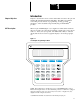
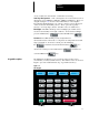
Chapter 1 Introduction Chapter Objectives Chapter 1 describes the various controls and indicators found on the optional Graphics Programming Terminal (1201 GPT). The GPT is an enhanced control that provides a means of programming, viewing operating parameters, on-line troubleshooting and analyzing of all SCANbusTM products. GPT Description When an optional GPT (Figure 1.1) is supplied, it will be either mounted to the front of a Drive as a panel mount terminal or supplied as a remote device with a 1.
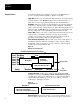
Chapter 1 Introduction Display Features Four different interface boxes (Figure 1.2) appear on the GPT display to provide you with pertinent information. These boxes include: Help Box: This box provides help information related to the function being currently displayed. The Help Box will provide you with information on what can be accessed or programmed using this specific menu function. Info Box: This box provides you with information about the data currently on the screen.
Chapter 1 Introduction used to indicate the selected letter or numeral in a text string. Soft Key Designators: Four soft designators are located at the bottom of the Display screen (SWFunc1, SWFunc2, SWFunc3, SWFunc4). These soft designators (Figure 1.2) are tied to the F1 thru F4 keys on the Graphics Programming Terminal (Figure 1.4). Various selection options will appear on the screen at the F1 thru F4 positions.
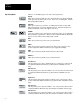
Chapter 1 Introduction Key Descriptions The keys on the GPT keypad control the following functions: ESC ESCape When pressed, this key will cause the current function to be aborted and will return you to the previous menu screen. In the case of a dialog box, only the dialog entry will be aborted. ALTernate When pressed, this key selects the secondary key functions for keys with ALTernate functions such as the Num/Preset keys. Alternate functions are always identified in (color) at the upper left of a key.
Chapter 1 Introduction XREF 1 A B C D E F 3 Numeric 3/Xref This key allows you to enter the number 3 or to select XREF 1 when used in conjunction with the ALTernate key. (ALT function on Runtime Version only). 4 Numeric 4/A This key allows you to enter the number 4 or to enter the letter A when used in conjunction with the ALTernate key. 5 Numeric 5/B This key allows you to enter the number 5 or to enter the letter B when used in conjunction with the ALTernate key.
Chapter 1 Introduction Optional Run Time Keys START The Start key will initiate drive operation if no other control devices are sending a Stop command. STOP If the drive is running, pressing the Stop key will cause the drive to stop, using the selected stop mode. Refer to the Drive user manual. If the drive has stopped due to a fault, pressing this key will clear the fault and reset the drive. JOG JOG When pressed, jog will be initiated if no other control devices are sending a stop command.
Chapter 1 Introduction In the case of a 1336 FORCE Drive equipped with a PLC Comm Adapter Board, eight menu options will be available as shown in Figure 1.7. When the Process Display Screen is active, it is necessary to press the Main Menu Option (F2 soft designator) on the Process Display to reach the Main Menu. The Main Menu contains the password option that provides a highlighted dialog box for password entry.
Chapter 1 Introduction Figure 1.8 details the complete menu tree for the GPT Programming Terminal. This menu is dynamic and all options may not be supported by your Drive or SCANbus device. If you need more detailed information on Key functions, Menu Screens or general Terminal operation refer to the appropriate chapter in this manual. Figure 1.
Chapter 1 Introduction > 1–9
Chapter 1 Introduction > 1–10
Chapter 2 Parameter Option General The Parameter Option provides you with access to the Drive parameter database. Any parameter can be directly accessed by number in the Linear Mode as shown in Figure 2.1, or any parameter can be viewed by File, Group or Element as shown in Figure 2.2. The Element option is accessed by pressing the Return key while the initial File/Group display is active. Figure 2.1 (Linear Mode Initial Screen) Linear: [ 142 ] Par < Vel Fdbk TP Low.
Chapter 2 Parameter Option Accessing the Linear Parameter Mode To access the Linear Parameter Mode from the Main Menu (Figure 2.3), press the Increment or Decrement key to move the cursor to selection #1 “Parameter”. Figure 2.3 Main Menu Main Menu: < 1 2 3 4 5 - > Help Parameter Link Summary Fault Queue Warning EEPROM Password ProcDspy Press the Enter Key , the terminal will go into either File/Group/Element or Linear Mode, depending on which mode was last used.
Chapter 2 Parameter Option Accessing a Parameter in the Linear Mode With the Linear Parameter Screen (Figure 2.5) displayed, perform the following steps: Step 1 Use the or key to scroll through the parameter numbers; or Step 2 If you wish to enter a parameter number directly, press the soft designator key. The dialog box shown in Figure F2 2.5 will appear. Figure 2.
Chapter 2 Parameter Option Figure 2.7 Linear Parameter Number Screen Linear: [ 90 ] Par < Value: Min: Max: Link: Stall Delay Absolute Overspd VP Warn/None Cfg VP Flt/Warn Cfg > Param # F1 Changing a Parameter Value 17.6 RPM 0 1750 None Val_Base F2 FGE Mode F4 F3 Move to the Value area of the screen by pressing the selection Key. The cursor will move to the current value in RPM. Figure 2.
Chapter 2 Parameter Option Use the or keys to change the value (Figure 2.9) or enter the value directly with the numeric keys. Figure 2.9 Parameter Value Change Value : Saving Parameter Values < 175.2 > RPM To save your new value in RAM, press the key. IMPORTANT: This is only necessary when a value is entered directly with the numeric keys. If the INC and DEC keys were used to enter the value, the value is automatically stored in RAM (Drive). To store your new value to BRAM, press the ESC key.
Chapter 2 Parameter Option IMPORTANT: If you are making more than one parameter change, it is not necessary to save every new parameter value at the time you make a value change. All parameter changes can be saved at one time using the EE/BRAM option detailed in Chapter 4. Accessing the FGE Mode In addition to accessing parameters one–by–one in the Linear Parameter mode, it is also possible to access parameters that have been grouped in special Files.
Chapter 2 Parameter Option Figure 2.12 File Selection Parameter: File < Grp Startup Communication IO Velocity / Torque Diagnostics File Monitor Testpoints Fault Sel / Sts Transistor Diagnostics > Group F1 Lin_Mode F2 Use the or choice and press the F3 F4 keys to place the cursors on your File key. In the example in Figure 2.13 you are in the Communication IO File and the Group options are available on the right hand side of the display. Figure 2.
Chapter 2 Parameter Option Group Selection When you selected your File option, the cursors automatically moved to the Group window on the right side of the Display. Use the or keys to scroll to your desired Group selection. Element Selection key to access the elements for this group (Figure 2.14). Press the Press ESC to return to the Group menu. Figure 2.
Chapter 2 Parameter Option Figure 2.15 Changing Element Values F - Communication IO G - Analog Output Elem Value : 0 Min : -32767 Max: +32767 Link: None An Out 1 Scale An Out 1 Offset < Analog Out 1> Val_Bas F1 F2 Use the Changing Value Base or Lin_Mode F3 F4 keys to change the Value reading. If you wish to work in a different Value Base, press the F3 soft designator key. The options shown in Figure 2.16 can be used. Figure 2.
Chapter 2 Parameter Option Figure 2.17 Base Value Selection F - Communication IO G - Analog Output Elem Value : < 0000 > Hex Min : 8001 Max: 7FFF Link: None < Analog Out 1> Val_Bas F1 Exiting the FGE Mode F2 F3 Lin_Mode F4 If you wish to exit the FGE mode and save any value changes, press the key twice. The verification screen in Figure 2.18 will appear. Figure 2.
Chapter 3 Fault & Warning Queues Introduction The Fault Queue and Warning Queue screens provide access to Fault and Warning Information stored in the drive. When you activate either the Fault Queue Entry Screen or the Warning Queue Entry Screen, the four (4) most recent faults or warnings will be displayed on the left hand side of the screen. In the case of faults, if the fault caused the drive to trip, a TP designator will precede the fault text string.
Chapter 3 Fault & Warning Queues Press the key to access the Fault Entry Queue (Figure 3.2). Figure 3.2 Fault Queue Fault Queue: < TP Power EEPROM FLT 02 - Fault Entry 2 03 - Fault Entry 3 04 - Fault Entry 4 Fault Info > Code: 2014 Time: Thu PM Dec 08, 1994 02:31:22:64 CLR_FLT CLR_FLTQ F1 F2 Drv_Res F3 Resolve F4 The latest four (4) fault entries will be displayed. If one of the four entries caused the drive to trip, a TP designator will precede the fault text string.
Chapter 3 Fault & Warning Queues To clear the Fault & Warning QUEUE without leaving a visual record, press the F2 soft designator. A verification request will appear (Figure 3.4). Figure 3.4 Clear Fault Queue Verification Message Clear Fault Queue Are you sure (Y/N) ? Press F1 soft designator for YES and F4 soft designator for NO. Upon successful completion of the clear, the #1 entry in the Queue will display CLEAR FAULTS to indicate the Queue has been cleared.
Chapter 3 Fault & Warning Queues Accessing the Warning Queue From the Main Menu, use the or key to place the cursor on Option 4, Warning Queue (Figure 3.6). Figure 3.6 Main Menu Options Main Menu: < 1 2 3 4 5 Help - Parameter - Link Summary - Fault Queue - Warning Queue > - EEPROM/BRAM ProcDspy F1 F3 F2 Press the key to access the Warning Queue (Figure 3.7). The four (4) most recent entries will be displayed. Figure 3.
Chapter 3 Fault & Warning Queues Clearing Warnings To clear the Warning Queue while still leaving a visual record of the warnings on the display, press the F1 soft designator. A verification request will appear (Figure 3.8). Figure 3.8 Clear Warning Verification Message Clear Faults/Warnings Are you sure (Y/N) ? Press soft designator for YES and F1 soft F4 designator for NO. To clear the complete Warning Queue without leaving a visual record, press the F2 soft key.
Chapter 3 Fault & Warning Queues This Page Intentionally Blank 3–6
Chapter 4 EE/BRAM Functions General The EE/BRAM Menu allows you to perform all non-volatile parameter storage functions. You can save parameter changes to the Battery RAM on the Adapter Board, save any process display changes you have made, or reset the parameter table to initial values using this menu. A help text box will appear with each menu option describing the selected options.
Chapter 4 EE/BRAM Functions Saving Parameters to EE Select option two (2) in the EE/BRAM menu with key. Press the or key to select the storage function. The display will respond with the question in Figure 4.3. Figure 4.3 EE Parameter Save Verification Store Data Parameters Are you sure (Y/N) ? To store all parameters to the non-volatile electronically erasable storage press the F1 soft designator (YES). To escape this function and return to the EE/BRAM menu, press the F4 soft designator (NO).
Chapter 4 EE/BRAM Functions Saving Factory Defaults to RAM To reset the parameter values to initial factory default values, choose option four (4) in the EE/BRAM menu with the Press the or key. key to select this option. The display will respond with the question in Figure 4.5. Figure 4.
Chapter 4 EE/BRAM Functions This Page Intentionally Blank 4–4
Chapter 5 Link Summary General This Main Menu option allows you to evaluate and change links in the system. The Sink parameter will always be displayed on the left side of the display and the Source parameter on the right. Each parameter will also display a File, Group and Element text string. There are four types of link options that you may use for inter-linking within a system. These include: 1. Parameter to Parameter links 2. Parameter to Function Block Node links 3.
Chapter 5 Link Summary Press the key to access the links currently in the system. The display will now show the first parameter in the system (Figure 5.2). Figure 5.2 Initial Link Screen Link Summary: Sink Parameter : < 20 > F Communication IO G Drive to Drive E D2D Xmit Data SRC Parameter: None Sel_Type NXT_Link Clr_All In this case, parameter 20 (Drive Link Transmit Data 1) is not currently linked to another parameter.
Chapter 5 Link Summary Changing or Adding Parameter Links Scroll to the Sink parameter you wish to link to another parameter by using the or key or the search function ( ) key. Press the key to move the cursor to the source field (SRC Figure 5.3). Figure 5.
Chapter 5 Link Summary Saving Parameter Links Once you have entered all changes to Sink and Source links, press the ESC key to save these links. The verification message in Figure 5.4 will appear. Figure 5.4 Save Link Verification Message Do you Wish to Save Parameters/Links (Y/N) ? To save all links, press the F1 soft designator (YES)). To escape the Link Verification and return to the Main Menu without saving your changes press the F4 soft designator (NO).
Chapter 5 Link Summary Figure 5.6 Clear Link Verification Message Clear all Parameter Links are you sure (Y/N) ? Yes No F1 F3 F2 To clear all links, press the F1 F4 soft designator. To leave all the links intact and return to the Previous Screen, press the F4 soft designator.
Chapter 5 Link Summary 5–6
Chapter 5 Link Summary Changing or Adding Function Block Links From the Link Summary Screen, press the F1 soft key and the display shown in Figure 5.7 will appear. Figure 5.7 Link Type Selection Enter Link Type : < 0 - Parameter > 1 - Func Blk Choose the Function Block Option by pressing PRESET 4 1 and then . The Display shown in Figure 5.8 will now appear.
Chapter 5 Link Summary Figure 5.8 Node to Parameter Display Link Summary Sink Node : : :< D2D Baud Rate Src Parameter : FGE- IMPORTANT: The screen shown in Figure 5.8 allows you to enter the information needed to Link a Node to a Parameter for Function Block linking. The Node to Parameter; Parameter to Node; and Node to Node; options are currently non–functional. Only Option 0, Parameter to Parameter linking should be attempted at this time.
Chapter 6 Clock Data General This Main Menu option allows you to program clock and time functions within the Drive. The software function keys are programmed to allow you to set the clock (Set_Clk), set the time reference (Set_Ref), zero the accumulator (Zero_Acc) or load the clock into reference (Load_Ref). Accessing the Clock Data Function From the Main Menu, use the or key to place the cursor on Option 6, Clock Data (Figure 6.1). Figure 6.
Chapter 6 Clock Data Press the key to access the Clock Data Main Display (Figure 6.2). Figure 6.2 Clock Data Main Display Clock Data: 12 HR" Clock Jan 05, 1995 04:35:49 Thu PM Set_ClK Accum Refer Jan 01, 1995 01:20:06 Mon AM Set_Ref 0 Hours Load_Ref Zero_Acc Setting the Clock From the Clock Data Main display, press the F1 soft designator to access the Set Clock display (Figure 6.3). Figure 6.
Chapter 6 Clock Data Setting the Reference This option allows you to set the reference manually to a specific date & time for record keeping purposes. From the Clock Data Main Display press the F2 soft designator key to access the Set Reference Display (Figure 6.4). Figure 6.
Chapter 6 Clock Data Loading the Reference This option allows you to load the current Date and Time into the reference for record keeping purposes. From the Clock Data Main Display, press the F3 soft designator key to load the clock into reference. The verification screen shown in Figure 6.5 will appear. Figure 6.5 Load Reference Verification Display Load Reference Stamp Are you sure (Y/N) ? To load the current clock reference press the F1 soft designator (YES).
Chapter 7 Process Display General The Process Display option can supply you with information on up to six (6) programmed process variables. The process variables will allow you to monitor the programmed parameter, scale it with the scale factor and add a customized text string. You also have the option of displaying different types of information on the right hand side of the display in the mode window. The Mode options that are available include: 1. An AB Logo Graphic 2. A Drive Status Report 3.
Chapter 7 Process Display Figure 7.1 Process Display Screen Ä 0.00 FREQ CMD 0.00 VEL FB 0.00 COMP PWR 0.00 MTR VFB 0.20 MTR I FB 0.00 TORQ FB ConFig Main Menu Dsp_Mode F2 F3 F1 F4 In this case the Process display came up in the AB–Logo mode. Accessing the Drive Status Mode To access the Drive Status Mode from the initial Process Display, press the F3 soft designator key. The Mode entry window in Figure 7.2 will appear. Figure 7.
Chapter 7 Process Display Press the PRESET 5 key to enter the number 2 and then press 2 to call up the Status Mode (Figure 7.3). Figure 7.3 Status Mode (Option 2) 0.00 FREQ CMD 0.00 VEL FB 0.00 COMP PWR 0.00 MTR V FB 0.20 MTR I FB 0.00 TORQ FB ConFig Accessing the Metering Mode Info Sts: Not Enabled Dir: Forward Out: Main Menu Press the Dsp_Mode F3 soft designator key to call up the Mode selection window (Figure 7.2).
Chapter 7 Process Display Accessing the Configuration Mode From any Process Display window press the F1 soft key to call up the Configuration display (Figure 7.5). Figure 7.5 Configuration Display < 0.00 FREQ CMD > Data 0.00 VEL FB 0.00 COMP PWR 0.00 MTR V FB 0.00 MTR I FB 0.00 TORQ FB Program Disabling a Process Display Variable Disable Parameter: 266 Scale: +1.
Chapter 7 Process Display Recalling a Process Display Variable If you have removed or disabled one Process Display variable and wish to recall it from the drive, place the cursors on the selected Process Display or location with the F3 key. Press the soft designator and the parameter will be restored to the Process Variable list.
Chapter 7 Process Display Figure 7.8 Configuration Scaling Display Config: Var #3 Data Min: -100.0 Max: +100.0 Parameter: 182 Scale: < +1.0 > Text: Computed View 0.00 Computed When the new scaling value is entered correctly, press the ESC key to save the value and return to the Main Configuration window. Changing the Configuration Text: Place the cursors (< >) on the Text variable using the key.
Chapter 7 Process Display the new letter or character you wish to enter, press the to save this new character. If you wish to delete the complete word and enter a new word, press the F4 soft key to blank out the complete text line. It is also possible to enter the text in hex. Press the F3 soft key to activate the Char_Val option. The display will respond with the window shown in Figure 7.10. Figure 7.
Chapter 7 Process Display This Page Intentionally Blank 7–8
Chapter 8 Special Menu General The Special function is a dynamic list of options that varies with the Drive State and the Drive Product being used. Options that may be available under the Special Menu include Autotuning, Trending, Diagnostics, Password, Drive Identity and Version information. Each option has a Help box that describes the function of this option. Accessing the Special Menu Function From the Main Menu, use the or key to place the cursor on option eight (8) Special (Figure 8.1).
Chapter 8 Special Menu Press the key to access the Special Menu (Figure 8.2). Figure 8.2 Special Menu Special Menu: < 4 - Change Password Help 5 - Version Info 6 - Drive Identity 7 - Data Transfer Changing & Entering a Password From the Special Menu use the or cursor on option four (4) Change Password. Press the access the Change Password display (Figure 8.3). Figure 8.
Chapter 8 Special Menu Enter the current password within the cursors using the numeric keys. If there is currently no password assigned, press the PRESET 2 0 key and then the key. The New Code request will appear as shown in Figure 8.4. Figure 8.4 New Code Request Old Code: ? < > New Code: Enter your new code with the numeric keys and then press the key. The GPT will respond with the message in Figure 8.5. Figure 8.
Chapter 8 Special Menu Inspecting Version Information From the Special Menu, use the or key to select key and the display will option five (5) Version Info. Press the show the current version of the GPT, and all processors in the drive (Figure 8.6). Figure 8.6 Version Information Display Version: B 1336T Vector GPT VP CP AP DP SW = V 0.04 SW = V 1.02 SW = V 1.02 SW = V 1.02 SW = V 1.01 LM = V 0.04 LM = V 1.02 LM = V 1.02 LM = V 1.02 LM = V 1.
Chapter 8 Special Menu Changing Drive Identity From the Special Menu use the or option six (6) Drive Identity. Press the key to select key and the Drive Identity display in Figure 8.7 will appear. Figure 8.7 Drive Identity Display Drive Identity Data ! I # $ % & ( ) * +, - .
Chapter 8 Special Menu To enter the first character press the PRESET 4 1 key and then the key. The $ sign will now appear at position 1 indicating the first character can be entered or changed at this point (Fig. 8.9). Figure 8.9 Character Entry Indicator Data ! I # $ % & ( ) * +, - . / 0123456789:;<=>? @ABCDEFGHIJKLMNO PQRSTUVWXYZ[\]∧_ \abcdefghijklmno pqrstuvwxyz(!)~ Name: $ --(Char # 1)-- Use the or key to scroll through the character selection chart on the right side of this display.
Chapter 8 Special Menu Continue the entry process by pressing the F1 soft designator and then entering number 2 in the character entry box. Enter your desired character for position #2. Continue this sequence until you have entered as many name characters as you wish, up to a maximum of sixteen. When you have entered all Drive Identity name characters as you wish them key. The new name will be saved and the to appear, press the display will return to the Special Menu.
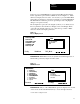
Chapter 8 Special Menu Accessing the Data Transfer Function From the Special Menu use the or key to select key and the Data Transfer Option 7; Data Transfer. Press the display will appear as shown in Figure 8.13. Figure 8.13 Data Transfer Display Data Transfer < 1 – Param File X Fr Data / / 0 Upload Uploading / / / / 50 100 (0)% Download To Upload the Param File, press the F1 soft designator key. The verification message shown in Figure 8.14 will appear. Figure 8.
Chapter 8 Special Menu Figure 8.15 Parameter File Upload Data Param Upload: – Rcv Par# :313 I 0 I 50 I 100 (62)% To cancel an Upload press the Downloading F4 To Download the Parameter File press the soft designator key. F2 soft designator while in the Data Transfer Display. A verification message will appear as shown in Figure 8.16. Figure 8.
Chapter 8 Special Menu When you press the F1 soft designator key the Download display shown in Figure 8.17 will appear. Figure 8.17 Parameter File Download Data Param Dnload: – Xmt Par#: 130 I I 0 I I 50 I I 100 (25%) A bar chart will scroll across the bottom of the Data Display to indicate the percentage of the parameter table that is downloaded. To cancel a download press the 8–10 F4 soft designator.
Allen Bradley, a Rockwell Automation Business, has been helping its customers improve productivity and quality for more than 90 years. We design, manufacture and support a broad range of automation products worldwide. They include logic processors, power and motion control devices, operator interfaces, sensors and a variety of software. Rockwell is one of the world's leading technology companies. Worldwide representation.