
Owner's Manual


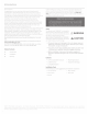
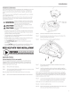
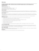

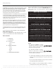
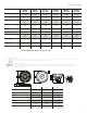
Table Of Contents
- RFX3-PMXDK Installation & Operation
- PMX-2 Installation & Operation
- RM1652B Installation & Operation
- Front Speaker Enclosure Installation & Operation
- Front Subwoofer Enclosure Installation & Operation
- RM110D2B Subwoofer Installation & Operation
- TM400X4ad Amplifier
- Amplifier Installation Kit Installation & Operation

Installation Considerations
This section focuses on
so
me considerations for installing your Can-
Am
Maverick
X3
subwoofer kit. This subwoofer enclosure
is
d
es
igned
to
work in conjunction with Rockford's
other
X3
specific audio kits and
pa
rts.
If
yo
u feel unsure
about
insta lling this sys
tem
your
se
lf,
have
it
i
ns
talled
by a qualified technician.
When d
ri
lling holes, make
su
re
what
is
on the other side.
Be
sure that
any electrical, fuel
li
nes or any other
imp
or
tant components are fr
ee
and clear from the area.
~WARNING
A CAUTION
A CAUTION
Before install
at
ion, disconnect the battery
negative(-) terminal to prevent damage
to
the unit, fi
re
an
d/o
r possible i
nJu
ry
.
Before beginning any installation, foll
ow
these simple rules:
Be
sure
to
carefully read and understand the
instructions bef
or
e atte
mpting
to
install this
wiring kit.
Co
nsult your
UTV
's
se
rvi
ce
manual for
mode
l sp
ec
ific inform
at
ion.
Models may differ from
yea
r to year depending on factory
op
tions
and aftermarket accessories added.
• Th
is
subwoofer kit is specifically designed to work
with
Roc
kford
Fosgate's
RM
series
of
s
ubwoof
ers.
Wi
th the addition of an amplifier
or
source uni
t,
be s
ur
e
that
your
curr
e
nt
charging
sys
tem is
in
proper
wo
rking order.
Vis
it
rockfordfosgate.com for more co
mp
rehensive product
information.
• Vis
it
our
YouTube channel for comprehensive installation videos
demonstrating complete installation guid
es
a
nd
insta ll tips.
NEED
HELP
WITH
YOUR
INSTALLATION?
@
¥OUTUBE
VISIT
OUR
CHANNEL
FOR
A
COMPLETE
I
1
INSTALLATION
VIDEO
AND
OTHER
TIPS
WWW.YOUTUBE.COMIUSERIROCKFORDFOSGATE
Applicable Models:
Can-Am Maverick
X3
{2
8c
4 seat models)
This
front
sub
woo
fer enclos
ur
e is d
es
igned to w
ork
with Rockford
Fo
sga
te's R
FX3
-
K4
I
RFX
3-
K8
amp
li
fier wiring kits.
Th
e enclos
ur
e is
installed in both 2-
sea
t and 4-
sea
t models on the driver side
of
the
vehicle underneath the fr
on
t
sea
t.
St
ep
1.
Re
move
th
e driver side
sea
t.
Step
2.
Re
move
th
e panel bel
ow
the shifter
to
gi
ve
you access to route
the su
bwoo
fe
r enclosure harn
ess.
NOTE:
Routing harne
ss
will be done after enclos
ur
e is mounted.
Step
3.
Remove the
br
acket that holds
th
e brake line
to
the chassi
s.
Installation
'
Brake Line
Step 4.
Place the sub
woo
fer
en
closure
into
the
vehicle.
Step
5.
R
out
e
the
brake line above the enclosure and
re
attach the
brake line b
ra
cket
to
the vehicle.
Step
6.
Secure
the
enclosure
wit
h supplied hardware.
Step 7. Drill
(4
) holes through the bo
tt
om skid plat
e.
Secure
wit
h
supplied hardware.
Step
8.
Load the subwoofer
int
o the enclos
ur
e us
in
g the supplied
screws that came w
ith
the woofer. The su
bw
oo
fer protective
g
ri
lle will be installed.
N
OTE:
Be
sure
to
ma
int
ain proper pola
rit
y and
im
pedance rating for
the
amp
lifier being us
ed
for this installation. When using a RM
11
0D2B
s
ub
w
oo
fer, be sure u
se
the su
pp
lied Red wi
re
to
wire the subw
oo
fer in
se
ri
es
to achieve a 4 ohm load.
Step
9.
Co
nn
ect
the s
ubw
oo
fer harn
es
s
to
enclos
ur
e and r
out
e the
w
1r
e
ha
rn
ess
throug
h the c
en
ter
console and up the dash.
N
OTE:
Be s
ur
e
to
u
se
suppli
ed
plastic wi
re
ti
es
to
se
c
ur
e harne
ss.
Step 10. Connect
to
radio harn
ess
.
Step
11.
P
ower
up the
sys
tem
an
d
ve
rify all functions. Once don
e,
the
vehicle
ca
n be reassembled in rever
se
orde
r.
3