
Owner's Manual
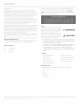
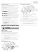


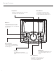

Table Of Contents
- RFX3-PMXDK Installation & Operation
- PMX-2 Installation & Operation
- RM1652B Installation & Operation
- Front Speaker Enclosure Installation & Operation
- Front Subwoofer Enclosure Installation & Operation
- RM110D2B Subwoofer Installation & Operation
- TM400X4ad Amplifier
- Amplifier Installation Kit Installation & Operation

Installation Considerations
This section focuses
on
some considerations for installing
your
Can-Am
Ma
verick
X3
dash kit. This dash kit
is
designed to
work
in conjun
ction
w
ith
Rockford's
other
X3
specific
audio
kits and parts.
If you feel unsure
abo
ut
installing
thi
s system yourse
lf
, have
it
installed
by a qualified technician.
When
dr
illing holes, make sure
what
is
on
the
o
ther
side.
Be
sure
that
any electrical, fuel lines
or
any
other
impor
ta
nt
components
are free
and clear from
the
area.
&WARNING
A
CAUTION
A
CAUTION
Before installation, disconnect
the
battery
negative(-)
terminal
to
prevent damage
to
the
unit, fire and/or poss
ibl
e injury.
Before beginn
in
g any insta llatio
n,
foll
ow
these
simple
rules
Be sure
to
carefully r
ea
d and understand the
instructions before
attempting
to
install this
wiring kit.
Consult
your
UTV
's
se
rvice manual f
or
model
sp
ecific
inf
orma
ti
on
.
Models may
diff
er
from
year
to
year
depend
ing on factory o
pt
i
on
s
and aftermarket accessori
es
added.
• This dash kit is specifically designed
to
wo
rk
with
Rockford
Fosgate's
compact
sour
ce
units.
Wi
th
the
addition
of
an amplifier or source
uni
t, be s
ur
e
that
y
our
current
charging system is in
proper
working
order.
Vis
it
rockfordfosgate.com
for
more c
ompreh
ensive pro
du
ct
inform
ation.
• Vis
it
ourYouTube channel for comprehensive
in
stalla
tion
videos
demonstrating
complete
ins
tallation
guides and install tips.
NEED
HELP
WITH
YOUR
INSTALLATION?
-@v:ouJUBE
VISIT
OUR
CHANNEL
F
OR
A
COMPLETE
I'
INSTALLATION
VIDEO
AND
OTHER
TIPS
WWW.YOUTUBE.COMJUSERJROCKFORDFOSGATE
Applicable
Models:
Can-Am Maverick
X3
{2 & 4 seat models)
This
da
sh
kit
enclosure is
de
signed
to
work
with
Ro
ckford
Fo
sgate
's
RFX3
-
K8
I
RFX
3-
K4
amp
lifi
er
wiring
kit
s a
nd
c
ompact
so
ur
ce
unit
s.
The
dash
kit
can be installed in
bo
th 2-seat a
nd
4-se
at
model
s.
Step
1.
Remove the
fu
se cover from on t
op
of
th
e dash. The new
da
sh
k
it
will replace
thi
s pi
ece.
S
tep
2.
Ne
xt you
wi
ll predrill (2)
hole
s using an
1/8"
dr
ill bit.
Temporarily set the dash piece
into
place to locate
th
e holes
that
need
to
be drilled.
NOTE:
There are
dimp
les from the factory
that
should line up
with
the
dash
kit
piec
e.
Dash Kit with PMX-2/PMX-3 Option
Installation
Dash Kit Assembly
with
PMX-0 Option
Step
3.
Mount
the
source
unit
to
the
new
dash piece using
the
supplied
mounting
screws and bezel.
Step 4. Route the wire harness
dow
n
the
ope
ning behind the fuse
block and
under
the
dash.
Step 5. Connect the Power and
Gr
ound
to
th
e
fa
c
tory
accessory
plu
g
underneath
the
dash.
NOTE:
When using
the
PMX
-0
yo
u
will
need
to
use the PMX-0 harness
for
Power a
nd
Grou nd along
with
connec
ting
the Yellow
wire
to
the
battery.
Step
6.
Plug t he harne
ss
in
to
the ba
ck
ofth
e s
our
ce unit.
Step
7.
Mount
the
asse
mb
led dash k
it
onto
the
top
of
the
dash and
insert
th
e rear
tab
s in
to
t
he
fuse cover slots.
Step
8.
Secu re dash
kit
using the su
pp
lied screws using a
T-
25 Torx.
3