
User guide
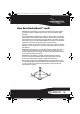


7RF-RBWS02
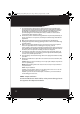
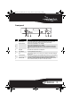
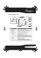
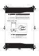
Front panel
# Feature Description
1
Power/Join button Press to turn the sender/receiver on, then hold to initiate joining. Press again to go into
standby. Upon insertion of the AC adapter, the unit powers up automatically.
2
Power/Join indicator Lights blue when the HUB STATUS is set to “DISABLE”.
Lights green when the HUB STATUS is set to “ENABLE”.
The LED will show a solid illumination when it is joined in a network, if the unit is not in a
network the LED will flash slowly. When the unit is put in joining mode the LED will flash
rapidly.
3
Standby LED Turns red when the sender/receiver is in standby mode.
4
IR sensor window Receives the signal from the remote control.
5
Source Press the next source button to move to the next source. Each press of the button will toggle
to the next source.
6
Receiver-mode LED Turns blue when receiving signals. Note: This LED will not be lit if the source unit is turned off
or is no longer sending audio. Press the Source button to find the next available source.
7
Sender-mode LED Turns blue when sending signals. Note: This LED will light automatically when a 3.5 mm
connector is attached to the unit, as the device senses the cable connection.
TM
1
2
3
4
5
6
7
RF-RBWS02_09-0535_MAN_ENG_V1.fm Page 7 Thursday, August 27, 2009 7:39 PM