Rocket Drones Stage 1 Kit Instruc�on Manual
TABLE OF CONTENTS 1. Product Overview 2. Package Includes 01 02 3. Quadcopter OSD Menu Operation 02 3.1 3.2 3.3 3.4 02 03 03 04 Device Introduction Device Features Device Overview Device Description 4. Launch Controller 06 4.1 4.2 4.3 4.4 06 06 07 08 Device Introduction Device Features Device Overview Device Description 5. Fat shark Goggles 13 5.1 5.2 5.3 5.4 13 13 13 14 Device Introduction Device Features Device Overview Device Description 6. LED Light/ Beep Status codes 22 6.
1.
2. Package include: • 1 x Rocket Drone • 1 x Launch Controller • 1 x Fat Shark Scout Goggles Box Contents: • • • • • • • • • 10 x BT2.0 450 mAh 1S Lipo Battery 1 x BT2.0 Battery Charger and Voltage Tester 1 x USB Charging Cable (Type-C) 1 x Type-C to FC Adapter 1 x Prop Removal Tool 4 x 31mm 4-Blade Prop (Replacement) 1 x Portable Storage Card 1 x User Manual 1 x Six port battery charger 3. Stage 1 rocket drone 3.
3.2 Device Features: • • • • • • • Self-protection Emergency Landing Function Turtle Mode 3 Flight modes Compatible with FPV Beginners Altitude hold Function Training-friendly 3.
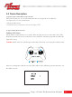
3.4 Device Description: 1. Quadcopter OSD Menu Operation: The OSD menu is a set of operation interfaces designed to modify the configuration of the quadcopter. • Turn on/off sensor. • Add/Remove information from the flight OSD. 2. Operation Instructions: Setting OSD Menu: The position of joysticks to access the OSD setting menu is as shown below. The throttle joystick is moved to the left-center and the direction joystick towards the upward center.
The OSD menu cursor can be controlled by the right joystick to operate the OSD interface: • Up: move the cursor up • Down: move the cursor down • Right: confirm/modify selection Customizing OSD Flight information: The information displayed in the OSD flight interface can be customized. This information includes receiver protocol, flight mode, battery voltage, and speed threshold. • In the MAIN menu, select LAYOUT and enter the LAYOUT menu, as shown below.
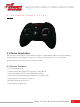
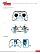
4. Launch Controller: 4.1 Device Introduction: The launch controller is a rcontroller designed primarily for RC models, including multi-copters and airplanes. It gives you more than you have ever thought possible from an entry-level 8-channel radio. 4.2 Device Features: • • • • • • • 8 channels in total. USB Joystick supports most practice simulators. Nano module bay for external RF TX module. New designed joystick gimbal for longer usage life. Frsky protocol version for option. Built-in 2000mAh battery.
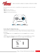
4.3 Device Overview: Front View: Power Button LED Ring Throttle Joystick Direction Joystick Upper View: Switch C Switch B Switch D Switch A Back View: NANO Bay SETUP BIND NC CRSF .
4.4 Device Description: 4.4.1 Button Functions: There are three buttons on the Launch controller. • Power Button: Turn the Launch controller on/off. • BIND Button: Enter binding mode after the Launch controller is powered on. • SETUP Button: Enter joystick calibration mode after the Launch controller is powered on. 4.4.2 Operation Instructions: 1. Power On/Off: • Power On: Long press the power button on the Launch controller for 3 seconds until it beeps three times (do re mi) then release.
2. LED Indicator and Buzzer: The LED ring indicates the working status of the Launch controller. The buzzer will alarm three times, which indicates a low battery and needs to be recharged. 3. Binding the Receiver: There are the steps to make the launch controller enter binding status; i. Power on the Launch controller and wait for its system to load completely. The LED ring will be solid blue if done correctly. ii. Press the “Bind” button on the back of the Launch controller to enter binding status.
Frsky Version LED Status Protocol Version Red Flash once Internal Frsky D16 FCC (ACCST 1.X Version) Red Flash twice Internal Frsky D16 LBT (ACCST 1. X Version) Red Flash Three Times Internal Frsky D8 Red Flash Four Times Internal Futaba S-FHSS Purple Flash Three Times Quickly Internal TX Module O and Run External TX Module To change protocols and TX module, here are the steps: i. Power the Launch controller off. ii. Press and hold the BIND button while powering the Launch controller back on.
5. Charging: The launch controller has a built-in 2000mAh battery. It indicates a low battery and needs to be re-charged if blue light ashes slowly the buzzer beeps continuously. Below charging method for reference: • Turn off the Launch controller. • Plug-in Launch controller with the adapter by USB cable (5V output adapter is allowed). • The LED ring breathes in red means charging, while in green means fully charged. Output 5V Type-C Data Cable 6.
Operation steps below: • Turn on the Launch controller. • Connect the Launch controller to the computer via a USB data cable. Wait for the LED ring breathes in red or green. • Install driver from PC automatically, prompt box pops up after successful installation. Then, the Launch controller works as a joystick human interface device (AKA HID device) normally. Note: The user needs to manually install the driver if the PC doesn't install automatically or is installed incorrectly.
5. Goggles: 5.1 Device Introduction: The Scout is a goggle packed with the latest technology including a built-in diversity receiver, a 60 FPS DVR, and everything necessary for amazing flights. It has been designed and tested to work with a wide variety of currently available NTSC and PAL analog Launch controllers as well as display video directly from an audiovisual or auxiliary source. 5.
5.3 Device Overview: Top View: Left View: Right View: 5.4 Device Description: 5.4.1 Button Functions: There are several user inputs on the device, the power button, the band and channel buttons, and the rocker switch.
1. Power Button: It has two functions; • The Short Press (less than 0.5 seconds), causes the LED to indicate the current battery life when the headset is turned off. • The Long Press (hold for 2 seconds or more), causes the device to turn on when the unit is powered off and turn off when the unit is powered on. 2. Band Button: It is active when the headset is on and has two functions; • The Short Press (less than 0.
Functions in the DVR playback: • The Long press of the center joystick will exit the file list interface or player interface. • The short press of the enter key will play back the recorded video by the unit. • The Up/Down on the joystick will select any file in turn. • The Left/Right on the joystick will move to page down or page up directly. 5.4.2 Operation Instructions: 1. The OSD: Band: The abbreviation for the radio frequency band that the headset is currently on.
We have set up a special set of “BAND L” that you can turn on in the menu if you want for experimental purposes. CH1:5362 CH2:5399 CH3:5436 CH4:5473 CH5:5510 CH6:5474 CH7:5584 CH8:5621 Channel: The current channel the headset is on (both the number and the actual radio frequency). Battery: The current battery life is shown by the icon and the percentage e.g. a %. 2. Changing Bands and RX Channels: To performs the functions, like; • To change the Band, the “CH+” button is used.
RX Channel LED Status LED Color Race Band CH1 Red Always On Race Band CH2 Orange Always On Race Band CH3 Yellow Always On Race Band CH4 Green Always On Race Band CH5 Light Blue (Cyan) Always On Race Band CH6 Dark Blue Always On Race Band CH7 Magenta (Pink) Always On Race Band CH8 White Always On ii. A long press on the Band button will cycle through the different RX bands in the following default order; a. Fat Shark to Race Band b. Race Band to Band E c. Band E to Band B d.
• As well as seeing the brightness or contrast change, the OSD will display the updated brightness (or contrast) level in the center of the image for 3 seconds. 4. Using an AV or AUX input: The Scout supports both AV and AUX inputs. • To use the AV or AUX input, plug the source into the appropriate port on the Scout headset. • Use the 5-way button to enter the options menu, go to the source sub-menu, and select AV or AUX. The image on the screen should show the input from the source.
Default mode of the DVR: The default mode of the DVR is to manually start and stop recording with a short press of the center of the “5-way” button. When you press the button to start recording, you should see a recording symbol in the upper right corner of the display as well as the duration of the recording on the OSD, support record DVR audio. Video Format: The DVR will create MOV files as it records. The files will be named in the following format: MOVYYMMDD-HHMMSS-#F.MOV.
Supported Formats: The Scout DVR supports both NTSC and PAL and is designed to support the *.MOV video formats. Playback: The DVR playback is accessed by selecting the “Playback” option from the DVR in the options menu. i. Once playback mode is selected, the DVR playback submenu is opened. This submenu contains a list of all video files currently on the device. ii. Pressing up/down on the “5-way” switch will navigate between files. iii.
viii. Long press on the “Center” button will return to file selection, long press on the “Center” button again will return the user to RX mode. 6. LED Light/Beep Status Codes: 6.1 Quadcopter LED Light: There are two RGB status LEDs on the bottom of the quadcopter.
Status LED Color Status State Description Solution Off The power on the quadcopter is abnormal or off Replace the battery and power on again Red Flashing slowly Quadcopter battery is low Replace the battery Blue Solid The quadcopter is connected with the remote control Launch controller Place the quadcopter on a horizontal surface and wait for awhile Blue Flashing fast The quadcopter is horizontal calibrating Disarm, and place the throttle joystick at the lowest position Purple Solid Qu
6.2 Launch Controller LED Light Status and Beep Codes: There is a blue & red LED indicator light around the power button which indicates the status of the launch controller.
7. Advanced Settings: Additional advanced settings are available in case of special operations. 7.1 Re-Bind for Quadcopter: In case of failure of connection between quadcopter and launch controller, the pilot may need to re-bind. To re-bind for Quadcopter follow the steps as follows; i. First, power on the quadcopter and wait until the loading of its system to complete. ii. With the help of a screwdriver lightly press the button on the quadcopter.
7.2 Quadcopter Level Calibration: After the quadcopter has taken off and landed several times, the quadcopter gyroscope may become offset. This will cause the quadcopter to always tilt in the same direction during a flight. To fix up the recalibration, follow the steps as follows: i. Turn on the quadcopter and the launch controller, and ensure that the connection is successful. ii. Place the quadcopter on a horizontal plane, and enter the quadcopter's OSD menu (Refer to "OSD Menu Operation"). iii.
7.3 Launch Controller Calibration: If the launch controller is subjected to physical impact, the joysticks may no longer read correctly and require recalibration. To re-calibrate the device, follow the instructions below; i. Power on the device, and press the “SETUP” button on the back of the launch controller which will beep twice, and LED will flash red twice quickly which shows the device has entered the calibration mode. ii.
Stage 1 Drone Kit Instruction Manual 28
8. Supplement: 8.1 Warning & Security: • Move the throttle joystick as gently as possible to avoid the quadcopter ascending and descending too suddenly. • Push switch SA down on the remote control Launch controller immediately if the quadcopter collides with any object. • Please try to keep motors perpendicular to the body. Otherwise, flight performance will be degraded. • Learn to control the quadcopter proficiently before flying in a large outdoor area or with the wind.
• If the battery has a peculiar smell, temperature, deformation, discoloration, or any other abnormal phenomenon, stop using the battery. Recycle and replace the battery. • If the battery connector gets dirty, please wipe it with a dry cloth before use. Avoid getting battery contacts dirty, which can cause energy loss or failure to charge. • Disposing of the battery randomly may cause a fire.
deformed by overexertion. Secondly, the distance between the replaced propeller and the motor is kept at about 2mm. There is no need to press down forcefully. Pressing down forcefully will cause damage to the motor or the blades to rub against the frame when working. 4 spare propellers are included: two each clockwise (CW) and counterclockwise (CCW). CW propeller warps clockwise. It is used on the front left or rear right motor. CCW propeller warps counterclockwise.
If the quadcopter needs to fly in an unsatisfactory environment, the optical flow positioning function can be turned off and the quadcopter will lose the auxiliary function of horizontal flight. This requires the pilot's better skills. Similarly, when the laser altitude determination function is turned on, try to avoid the following unsatisfactory environments: For the steps to turn off/on the positioning function or laser altitude determination function, please refer to the chapter of "Advanced Functions".
To connect your radio: • Turn on the launch controller and wait for the blue light to show. • Connect the launch controller with the PC by USB cable. • The correct driver will install automatically. A box pops up to confirm successful installation. Q: How to Stop After A Collision? A: Push down switch A on the launch controller immediately once the quadcopter collides with an object.
10. FCC STATEMENT : This device complies with Part 15 of the FCC Rules. Operation is subject to the following two conditions: (1) This device may not cause harmful interference, and (2) This device must accept any interference received, including interference that may cause undesired operation. Warning: Changes or modifications not expressly approved by the party responsible for compliance could void the user's authority to operate the equipment.
Specific Absorption Rate (SAR) information: This LAUNCH CONTROLLER meets the government's requirements for exposure to radio waves. The guidelines are based on standards that were developed by independent scientific organizations through periodic and thorough evaluation of scientific studies. The standards include a substantial safety margin designed to assure the safety of all persons regardless of age or health.