Toyota Tundra Step Slider Installation BS-SS-100-TUN Installation Instruction RSEI 131
PARTS LIST 1 DESCRIPTION Drivers Side Slider Assembly 1 Passenger Side Slider Assembly 1 Wiring Harness and Fuse 1 Double Sided Sticky Squares and Alcohol Pad 1 Cut Off Switch 1 Anti-Seize Packet 1 Control Box 2 Top Brackets 2 Back brackets 2 Grip Tape Strips 4 Actuating Magnets and Door Sensors 24 7/16” Washers 24 Aluminum Nutserts 14 5/16” SS Button Head Bolts 14 5/16” Stainless Steel Washers *Optional: 2 LED Light Strips Installation Instruction RSEI 131
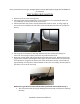
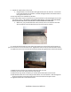
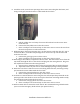
*If any parts listed are missing or damaged please call Rock-Slide Engineering @ 435-752-4580 prior to installation STEP SLIDER INSTALLATION 1. Remove the stock rocker panel guards 2. The top bracket will be installed first (If the brackets are not symmetrical make sure you install the correct bracket on the correct sid) 3. The back bracket start point is directly behind the rear door seam. It will go right up next to the spot welded pinch seam that curves around the back of the cab. (see photos below) 4.
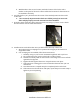
b. With bracket in the correct location, mark the location of the holes with a marker on the panel of the truck. These will be the locations for the nutserts to be installed in the body. 6. Carefully drill a 7/32’’ pilot hole into the center of the marked points into the truck’s rocker side a. **It is extremely important these holes are drilled precisely to insure the slider will fit properly once the nutserts have been installed 7.
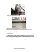
9. Attach the top bracket to the truck a. Hang bracket on truck and bolt through bracket into the nutserts. Leave bolts loose until all bolts are installed. Go back and tighten bolts until the bracket is firm against side of truck 10. Set step slider onto installed top bracket 11. Place step slider in place and put two countersunk bolts in the matching holes to hold the slider in place. BE SURE TO TIGHTEN THESE BOLTS. DO NOT OPEN THE DOOR WITH THESE PARTICALLY INSTALLED IT COULD DAMAGE YOUR DOOR. a.
18. Attach the slider to the top bracket using the stainless steel bolts. Don’t forget to use the anti-sieze on each stainless steel bolt 19. Tighten the bolts from the back bracket to the step slider body 20. These holes are elongated to allow for any adjustments that need to me made. 21. When the slider is mounted make sure that you have not twisted or manipulated the shape of the slider with you tightening sequence. THIS WILL CAUSE THE STEP TO NOT WORK PROPERLY. 22.
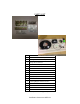
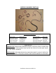
WIRING HARNESS INSTALL Step Slider Wiring Diagram Driver Side Front Door Sensor Rear Door Sensor Driver LED Light Driver Actuator Wire Color Orange/Yellow Orange/Pink Brown/Tan Red/Black Passenger Side Front Door Sensor Door Sensor Passenger LED Light Passenger Actuator Wire Color Green/Gray Blue/White Pink/Tan Red/Black **WARNING** REMOVE FUSE FROM WIRING HARNESS PRIOR TO INSTALLATION! CONNECTING THE HARNESS TO THE POWER SOURCE WITH THE FUSE ATTACHED MAY SHORT OUT THE WIRING HARNESS.
1. Remove the sill plate covers on both driver and passenger rear doors 2. Lay out the wiring harness on the carpet in the back seat 3. Split the harness into the driver’s and passenger side as instructed in wiring diagram above 4. Position the control box under the rear seat or near the back of the cab, anywhere out of the way where the wiring harness will fit to both sides of the truck. a.
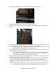
8. Inside the truck, route the rear passenger door sensor wire along the doorframe; and using a sticky pad, mount the sensor underneath the door latch a. Pull the rubber door seal away from near the latch and run the sensor wires under the seal. b. Connect the blue/white wire to the door sensor c. Place a small piece of electrical tape on the sensor wire to secure the wire from the truck and protect it on the metal seam 9. While moving to the front passenger door, run the harness under the door sill.
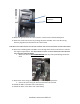
Possible switch locations 14. Mount the ground from the cutoff switch to a metal surface behind dash panel 15. Route the cutoff switch wires by running the POS+ and NEG- wires rom the wiring harness plug them into the back of the cutoff switch THE BRASS COLORED PRONG IS FOR THE GROUND THE SILVER COLORED IS FOR THE POWER 16. Route the remaining POS+ and NEG- wires through the firewall on the driver’s side into the engine compartment.
20. Position the actuating magnets on the catch side of each door a. Make sure the actuating magnets are in perfect line with the sensors b. **DO NOT allow the magnet and sensor to come into direct contact. This will destroy the sensor making it unusable** c. Once that proper placement is achieved we recommend using a permanent marker to outline the magnet on the door. 21.
TROUBLE SHOOTING/FRICTION POINTS The slider is powered by the truck’s battery when engine is off and powered by the Truck’s engine while the vehicle is running. This will cause the slider to operate at different speeds depending on if the truck engine is running or not.