TJ YJ LJ STEP SLIDER INSTALLATION BD-SS-100-TJ, BD-SS-100-YJ, BD-SS-100-LJ Installation Instruction RSEI 123
PARTS LIST QTY DESCRIPTION 1 Drivers Side Slider Assembly 1 Passenger Side Slider Assembly 1 Wiring Harness 1 Double Sided Sticky Squares 1 Cut Off Switch 1 Anti-Seize Packet 1 Control Box 2 Alcohol Wipes 2 Door Sensors & Actuating Magnets 2 Grip Tape 4 7/16” Nuts 4 7/16” Washers 8 5/16'' Hex Head Bolts 8 Steel Nutserts 8 Large Washers 10 Aluminum Nutserts 10 5/16” SS Button Head Bolts 10 5/16” Stainless Steel Washers *Optional: 2 LED Light Strips *If any parts listed
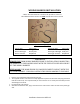
SLIDER INSTALL 1. Remove stock sliders from the Jeep, if equipped. 2. Use a floor jack or buddy to help hold the slider in place in order to mark holes to be drilled. Take extra care when positioning the slider on the Jeep rocker face to prevent any scratching or marring of the painted surface. The slider should be tight on the underside and to the rocker side of the Jeep. Take your time to ensure that the slider is installed straight and level.
5. Install nut inserts with an installation tool if available. If not, install by using a 5/16”x1.125” minimum length bolt with 3/8”nut. Put a small amount of grease on the bolt to reduce friction. Hold the nut steady with an end wrench so the flange of the insert is flush against the body panel. Tighten the bolt against the nut to crimp the nut insert in place. If the insert is rotating, place a star lock washer between the 3/8” nut and insert. Once it is crimped completely, back out the bolt.
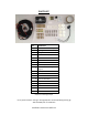
WIRING HARNESS INSTALLATION **Note: The same harness is used for the JK 4-door version ** The additional door sensors are NOT used for the 2-door version Step Slider Wiring Diagram Driver Side Front Door Sensor Driver LED Light Driver Actuator Wire Color Orange/Yellow Brown/Tan Red/Black Passenger Side Front Door Sensor Passenger LED Light Passenger Actuator Wire Color Green/Gray Pink/Tan Red/Black **WARNING** REMOVE FUSE FROM WIRING HARNESS PRIOR TO INSTALLATION! CONNECTING THE HARNESS TO THE POWER SO
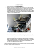
5. Divide the harness between the driver and passenger side. Mount the sensors on the driver and passenger side just underneath the door latch on the inside door frames using the sticky pads provided. Route the wires around the body seam by placing a small piece of electrical tape on the body seam. Wrap the wire over the top of the tape towards the inside of the cab then secure the wire with another piece of electrical tape. (shown above) 6.
10. Route the POS+ and NEG- wires through the firewall on the driver side. Make sure not to interfere with any of the pedal linkage under the dash. 11. Route wires along the firewall securing the 2 wires to the harness across the firewall. 12. Remove fuse and hook the NEG- to the NEG-side of the battery. POS+ to the POS+ side of the battery. 13. Position door sensor magnet on the catch side of each door. Make sure the magnet is in line with the sensor both on top and fore and aft.
MAINTENANCE OF THE STEP SLIDER Please note the slider is a mechanical mechanism that requires maintenance to operate properly. To keep the slider operating at an optimal level it needs to be maintained with lubrication. We recommend using a Teflon based lubrication on the 7 indicated points below to keep the slider operating smoothly. A good rule of thumb is every time you change your engine oil. Heavy trail use will increase the frequency in lubrication.