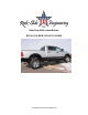
Ram Step Slider Installation BD-SS-100-RAM, .
PARTS LIST 1 DESCRIPTION Drivers Side Slider Assembly 1 Passenger Side Slider Assembly 1 Wiring Harness and Fuse 1 Double Sided Sticky Squares and Alcohol Pad 1 Cut Off Switch 1 Anti-Seize Packet 1 Spray Lubricant 1 Control Box 2 Top Brackets 2 Back brackets 2 Grip Tape Strips 2-4 4 Brackets (2 Crew Cab, 4 Mega Cab) Actuating Magnets and Door Sensors 24 7/16” Washers 24 1/2" Washers 24 Aluminum Nutserts 14 5/16” SS Button Head Bolts 14 5/16” Stainless Steel Washers *Option
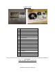
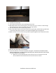
1. Remove the black rubber pieces covering the factory mounting holes on the bottom and back of the cab pinch seam. The back of cab pinch seam has 6 factory holes in pairs of two Hole with plastic removed Remove plastic cover 2. Insert a nutsert with a ½” washer into each of the holes and crimp into place a. We suggest using a crimping tool to optimize the integrity of the nutserts to support the slider b. If no crimping tool is available, follow these instructions i. Install by using a 5/16’’x1.
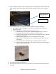
5. Hold the bracket up against the truck panel matching the body angles. Position the bracket so that the back of the bracket is up against the panel seam. This should leave the top of the bracket in approximately a level position when installed on the truck, providing a level bracket for the slider to sit on 6. Bolt the bracket to the truck using the 7/16” bolts and a 7/16” washers. Bolt through the bracket into the nutsert for each hole on the top bracket 7. Attach the top bracket to the truck a.
8. Install the back bracket 9. Line up the bracket holes to the matching factory holes 10. Bolt the bracket to the truck using the 7/16” bolts and a 7/16” washers. Bolt through the bracket into the nutsert for each hole on the top bracket 11. Set step slider body onto installed top bracket 12. Place step slider in place and ensure holes from top bracket and back line up with holes on the step slider body. Brackets can be adjusted slightly by loosening bolts. 13.
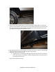
16. Make sure all bolts on the brackets and step slider are tight 17. Attach stiffening bracket from the step slider to the body mount bolt located closest to the center of the step slider 18. Loosen the body mount bolt to give room for the bracket without removing it all the way 19. Slide the stiffening bracket under the body mount bolt and large factory washer.
20. Bolt the bottom of the bracket into the step slider body with a 7/16” bolt and washer. Tighten the bolt into the step slider, then tighten the body bolt to make the bracket tight 21. When the slider is mounted make sure that you have not twisted or manipulated the shape of the slider with you tightening sequence. THIS WILL CAUSE THE STEP TO NOT WORK PROPERLY. 22.
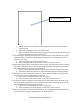
Step Slider Wiring Diagram Driver Side Front Door Sensor Rear Door Sensor Driver LED Light Driver Actuator Wire Color Orange/Yellow Orange/Pink Brown/Tan Red/Black Passenger Side Front Door Sensor Door Sensor Passenger LED Light Passenger Actuator Wire Color Green/Gray Blue/White Pink/Tan Red/Black **WARNING** REMOVE FUSE FROM WIRING HARNESS PRIOR TO INSTALLATION! CONNECTING THE HARNESS TO THE POWER SOURCE WITH THE FUSE ATTACHED MAY SHORT OUT THE WIRING HARNESS.
2. Lay out the wiring harness on the carpet in the back seat 3. Split the harness into the driver’s and passenger side as instructed in wiring diagram above 4. Position the control box under the rear seat or near the back of the cab, anywhere out of the way where the wiring harness will fit to both sides of the truck. a. Choose a location out of sight and in a secure spot so it will not come into contact with anything or be kicked by a rear seat passenger 5.
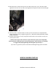
Door sensor installed a. Pull the rubber door seal away from near the latch and run the sensor wires under the seal. b. Connect the blue/white wire to the door sensor c. Place a small piece of electrical tape on the sensor wire to secure the wire from the truck and protect it on the metal seam 9. While moving to the front passenger door, run the harness under the door sill. Just as for the back door, route the front passenger door sensor wire up near the latch and under the door seal. a.
Recommended switch location THE BRASS COLORED PRONG IS FOR THE GROUND THE SILVER COLORED IS FOR THE POWER 14. Mount the ground from the cutoff switch to a metal surface behind dash panel 15. Route the cutoff switch wires by running the POS+ and NEG- wires rom the wiring harness plug them into the back of the cutoff switch 16. Route the remaining POS+ and NEG- wires through the firewall on the driver’s side into the engine compartment.
20. Position the actuating magnets on the catch side of each door c. Make sure the actuating magnets are in perfect line with the sensors d. **DO NOT allow the magnet and sensor to come into direct contact. This will destroy the sensor making it unusable** e. Once that proper placement is achieved we recommend using a permanent marker to outline the magnet on the door. 21.
TROUBLE SHOOTING/FRICTION POINTS The slider is powered by the truck’s battery when engine is off and powered by the Truck’s engine while the vehicle is running. This will cause the slider to operate at different speeds depending on if the truck engine is running or not.