JEEP JK2 STEP SLIDER INSTALLATION BD-SS-100-JK2 Installation Instruction RSEI 107
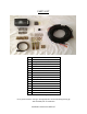
PARTS LIST QTY 1 DESCRIPTION Drivers Side Slider Assembly 1 Passenger Side Slider Assembly 1 Wiring Harness and Fuse 1 Double Sided Sticky Squares 1 Cut Off Switch 1 Anti-Seize Packet 1 Control Box 2 Alcohol Wipes 2 Actuating Magnets & Door Sensors 2 Grip Tape 4 3.
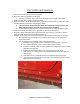
STEP SLIDER INSTALLATION 1. Remove the stock rocker guard if equipped. 2. Move the slider into position on the Jeep. a. You may want some help so that you can support the weight of the slider 3. Make sure the slider is in the position desired. 4. When the slider is in the desired position, carefully mark the 6 holes on the side of the Jeep that will be required for mounting the slider. a.
8. Lift the slider back into position and attach it to the Jeep using the 5/16” button head bolts and 5/16” washers. a. You will be using 6 bolts/washers per side b. Apply a small amount of anti-seize to the threads of each bolt upon installation 9. On the inside of Jeep remove the necessary plastic side panels and pull back the carpet along the door sides of the Jeep to expose the bottom tub. 10.
WIRING HARNESS INSTALL **Note: The same harness is used for the JK 4-door version ** The additional door sensors are NOT used for the 2-door version Step Slider Wiring Diagram Driver Side Front Door Sensor Driver LED Light Driver Actuator Wire Color Orange/Yellow Brown/Tan Red/Black Passenger Side Front Door Sensor Passenger LED Light Passenger Actuator Wire Color Green/Gray Pink/Tan Red/Black **WARNING** REMOVE FUSE FROM WIRING HARNESS PRIOR TO INSTALLATION! CONNECTING THE HARNESS TO THE POWER SOURCE
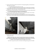
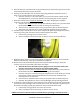
5. Once the harness is positioned in its proposed layout you will need to gain access to the slider outside the Jeep to power the slider. 6. Starting on the passenger side; locate the drain plug and drill a small hole into it to allow you to run the actuator wire to the slider. a. Once the actuator is run to the slider you can put some silicon sealant around the drilled hole to prevent any elements from entering, but it’s not required 7.
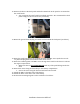
12. Remove the driver side dash panel and drill a 18mm hole in the panel to accommodate the cutoff switch. a. You can mount the cutoff switch in multiple positions. We recommend the dash panel simply for the ease off access (see below) 13. Mount the ground from the plug to a metal surface behind the dash panel (see below). 14. Route the cutoff switch wires by running the POS+ and NEG- wires up the driver side “A” pillar and plug them into the back of the cutoff switch. 15.
a. Make sure the actuating magnets are in perfect line with the sensors b. **DO NOT allow the magnet and sensor to come into direct contact. This will destroy the sensor making it unusable** c. Once that proper placement is achieved we recommend using a permanent marker to outline the magnet on the door. 20. Re-check all wires to make sure they are completely secure and free from coming into contact with any moving part to prevent system damage due to a cut wire. 21.
TROUBLE SHOOTING/FRICTION POINTS The slider is powered by the Jeep’s battery when engine is off and powered by the Jeep’s engine while the vehicle is running. This will cause the slider to operate at different speeds depending on the Jeep engine is running or not. If you feel the slider is sticking at certain points or the motor is stressing it may be possible a friction point has developed during the install due to a variance in the slider or Jeep construction.