
Technical data


64
Electrodes: check and repair in case of incorrect physical conguration, alumina •
deposits or degraded protective ceramic and gaskets.
Fumes limit thermostat and combustion unit: replace only after having identied •
the cause of the problem and made sure that it is not due to the heat exchanger
overheating. If you replace it, track the new component.
Extraordinary maintenance
The operations described in this paragraph must be carried out as and when necessary.
Adding water and antifreeze to the hydraulic plant.•
If it should become necessary to add water to the plant and, if required, to the water in
the plant (free of impurities) glycol antifreeze of the inhibited monoethylene type, for the
correct execution of these procedures, proceed as described in Paragraph 4.6 FILLING OF
HYDRAULIC CIRCUIT → 34.
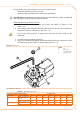
6.3 CHANGE OF GAS TYPE
This operation must be carried out exclusively by an authorised Robur Technical Assist-
ance Centre (TAC).
If the appliance is to be used with a type of gas other than that indicated on the sticker
inside the appliance (see detail M in Figure 6.2 Gas changeover → 65), switch o the ap-
pliance, shut o its power and gas supplies and proceed as follows:
You will need: the appliance switched o and disconnected from the gas/electricity
supplies
Disconnect the gas pipe from the gas valve.1.
Undo the 4 bolts E shown in Figure 6.2 Gas changeover 2. → 65 and remove the gas
valve/blower assembly from the burner.
Protect the burner from bolts and nuts falling into it.3.
Using a CH 4 hex key, undo the 4 bolts G indicated in Figure 6.2 Gas changeo-4.
ver → 65 and remove the nozzle D from the gas valve.
Replace the nozzle and o-ring C (see Figure 6.2 Gas changeover 5. → 65) with those
of the diameter suited to the new type of gas (see Table 6.2 Gas nozzles and con-
tent of CO2 → 65). The nozzle code is stamped on the nozzle itself.
Check that the o-ring B is tted.6.
Reassemble the gas valve to the blower with the 4 bolts G taking care that the red 7.
silicon hose between the venturi tube and the gas valve (see detail F of Figure 6.2
Gas changeover → 65) is correctly installed.
Replace the white gasket between the blower and the burner.8.
Reinstall the blower/gas valve assembly to the burner with the 4 bolts E, taking 9.
care not to damage the white gasket.
Reconnect the gas pipe to the gas valve.10.
Replace the sticker indicating the type of gas for which the appliance was set up 11.
(detail M of Figure 6.2 Gas changeover → 65) with one that indicates the new type
of gas used.
Check the tightness of the installation as follows:12.
Connect a manometer to the gas intake D (Figure 6.1 Gas valve • → 61).
Open the gas valve.•
Close the gas cock and check that the mains pressure has not dropped.•
If there is no gas leak, supply gas and electricity to the appliance and restart it.13.