
Technical data


62
E3-GS; E3-WS; E3-A; GAHP-GS; GAHP-WS; GAHP-A Gas supply pressure
Product categories Countries of destination G20 [mbar] G25 [mbar] G30 [mbar] G31 [mbar] G25.1 [mbar] G27 [mbar] G2,350 [mbar]
II
2ELL3B/P
DE 20 20 50 50
II
2Esi3P
FR 20 25 37
II
2HS3B/P
HU 25 30 30 25
II
2E3P
LU 20 50
II
2L3B/P
NL 25 50 50
II
2E3B/P
PL
20 37 37
II
2ELwLs3B/P
20 37 37 20 13
II
2ELwLs3P
20 37 20 13
I
2E(R)B ;
I
3P
BE 20 25 37
I
3P
IS 30
I
2H
LV 20
I
3B/P
MT
30 30
I
3B
30
If the pressure reading is not in line with Table 6.1 Network gas pressure → 61 DO
NOT activate the appliance!
Proceed with the regulation/verication of the combustion parameters as stated 5.
in the next paragraph.
Checking and adjusting the combustion parameters
After having checked the dynamic mains pressure (see section), you may check and ad-
just the combustion parameters as follows.
Insert the combustion products analysis probe into the vertical tract of the ue gas 1.
pipe (see reference B in Figure 4.4 Fume outlet → 36).
Give the unit functioning consent and wait for at least 5 minutes for normal com-1.
bustion conditions.
With the appliance running, access menu 2 parameter 24 of the unit's controller: 2.
the display will ash "P_H1", press to conrm forcing maximum thermal power .
Check that the value of CO3.
2
read on the ue gas analyser coincides with the value
given in Table 6.2 Gas nozzles and content of CO2 → 65 at the "Content of CO
2
with/MAX modulation" line with +0.2 -0.4 tolerance.
Example (G20 gas): the nominal content of CO
2
is equal to 9.1%, values in the range
between 8.7-9.% are therefore acceptable.
Access menu 2 parameter 23 of the unit's controller inside the electric panel: the 4.
display will ash "P_L1", press to conrm forcing minimum thermal power.
Now check that the dierence between the value read in point 4 and that now 5.
displayed on the ue gas analyser, corresponds to the data given in the Table 6.2
Gas nozzles and content of CO2 → 65 at the "Delta CO
2
between MAX and MIN
potentiality" line with tolerance of +0.3-0.0.
Example (G20 gas): if at point 4 a content of CO
2
equal to 9.2% was detected, at
point 6 there must be a value of (9.2%-0.4) with tolerance of +0.3 -0.0 on the delta
value, i.e. a value in the range of 8.8-8.5%.
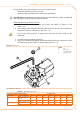
If this is not the case, remove cap A from the gas valve (see Figure 6.1 Gas valve 6. → 61)
and use a Torx TX40 wrench to act on screw C in Figure 6.1 Gas valve → 61. Turn
clockwise to increase the percentage of CO
2
and anti-clockwise to decrease the
percentage of CO
2
.
1/8 turn of the regulator screw reduces (counterclockwise) or increases (clockwise)
the CO
2
content by approximately 0.1%. DO NOT turn the screw more than one full
turn in either direction.