
Technical data


54
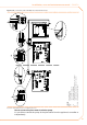
Figure 5.16 – Electrical wiring diagram
Example of pump/appliance electrical connection with 230 Vac pump, controlled directly by the appliance through a relay and a SELV safety
transformer
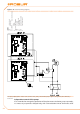
LEGEND
SCH electronic board
J10
jumper open
N.O. CONTACT clean exit normally open
L phase
N
neutral
Components NOT SUPPLIED
PMP water pump
KP control pump relay
GS
general switch
PTR safety transformer SELV
IP bipolar pump switch
Independent control of the pumps
If it is intended to manage the operation of the plant water circulation pump separately,
it is necessary to provide a delayed relay, with a de-excitation time of 10 minutes: after