
Technical data


Installation, user and maintenance manual – GAHP-A
53
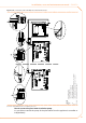
Figure 5.15 – Electrical wiring diagram
Example of pump/appliance electrical connection with 230 Vac pump (with absorbed power equal or more than 700 W), controlled directly by the
appliance through a relay
LEGEND
SCH electronic board
TER
terminal board
J10 jumper open
N.O. CONTACT clean exit normally open
L
phase
N neutral
Component NOT SUPPLIED
CS ON/OFF control switch
PMP
water pump =700W
KP control pump relay
GS general switch
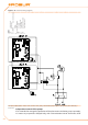
If several appliances are connected on the same hydraulic circuit, it is always necessary
to provide a safety transformer (secondary SELV) and a respective control relay; make the
connections according to the diagram in Figure 5.16 Electrical wiring diagram → 54.