
Technical data


48
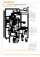
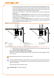
Figure 5.9 – Connection from CAN BUS to connector P8
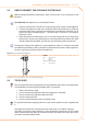
Connection detail of cable CAN BUS.
LEGEND
A Insulating tape to protect board/shield
B
CAN BUS cable wires
C CAN bus cable shield
D terminal and screw for xing
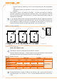
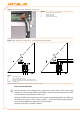
Figure 5.10 – detail wires and jumpers J21 - terminal/intermediate node DDC
Detail terminal and intermediate node: jumpers position J21: "closed" - "open".
LEGEND
DDC Direct Digital Control
J21
Jumper CAN-BUS in DDC board
A detail case "terminal node" (3 wires; J21=jumper "closed")
B detail case "intermediate node" (6 wires; J21=jumper "open")
H,L,GND
data signal wires
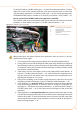
How to connect the DDC
The DDC requires a low voltage power supply (24 V) with a 230/24 V AC, 50 Hz safety
transformer; the minimum power requirement is 20 VA. For the connection use a cable
with the minimum specications 2 x 0.75 mm
2
.
Connect the DDC to the transformer via the 4-pole connector provide for this, following
the diagram in Figure 5.11 DDC - electric supply → 49. Pass the cable through the open-
ing in the cover before xing the wires to the connector.
To power up the DDC, proceed as follows.