
Technical data


46
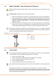
Fix the CAN bus cable (or two cables, according to the type of node being connect-7.
ed) to the cable xing bracket in the upper part of the inside of the electrical panel
so that the rolled-back sheathing makes solid contact with the metal bracket. The
cables must be held rmly in place by the bracket if pulled.
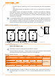
To position the jumpers on the board according to the type of node being
congured:
If the appliance is a • terminal node on the network (i.e. 3 wires are inserted in the
orange connector on the board): set the jumpers as shown in detail "A" of Figure
5.8 Electrical wiring diagram → 46:
If the appliance is an • intermediate node on the network (i.e. 6 wires are inserted
in the orange connector on the board); set the jumpers as shown in detail "B" of
Figure 5.8 Electrical wiring diagram → 46:
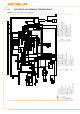
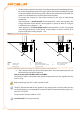
Figure 5.8 – Electrical wiring diagram
Connection cable CAN BUS to electronic board: detail A case "terminal node", detail B case "intermediate node"
LEGEND
SCH electronic board
GND
Common data
L Data signal LOW
H Data signal HIGH
J1 Jumper CAN-BUS in board
A Detail case "terminal node" (3 wires;
J1=jumper "closed")
B Detail case "intermediate node" (6
wires; J1=jumper "open")
P8
Port can/connector
After having carried out all the above operations, close the electrical panel and 8.
ret the front panel of the appliance.
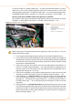
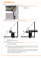
How to connect the CAN BUS cable to the DDC
The CAN bus cable is connected to the specic orange connector (P8) supplied with the
DDC in a bag.
Before working on the DDC, make sure that it is o.
The DDC, like the controller on the appliance, has jumpers that must be moved so that it
can be congured as an intermediate or terminal node. The position of the jumpers on a
new DDC is CLOSED.
To connect the CAN bus cable to a DDC:
You will need: DDC not powered up.