
Technical data

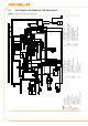


Installation, user and maintenance manual – GAHP-A
45
As shown in Table 5.2 CAN BUS cables type → 44, the CAN connection requires a CAN bus
cable with 3 wires. If the available cable has more than 3 coloured wires, use the wires
with the colours indicated in 5.2 CAN BUS cables type → 44 and cut the remaining ones.
The ROBUR NETBUS cable is available as an accessory, see Section 7 ACCESSORIES → 67.
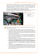
How to connect the CAN BUS cable to the appliance's controller
The CAN BUS cable must be connected to the special socket on the machine’s on-board
controller, as shown below (see Figure 5.7 CAN BUS cable connection → 45).
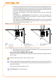
Figure 5.7 – CAN BUS cable connection
Example of a single CAN bus cable connected to the board
LEGEND
A Insulating tape to protect board/shield
B
CAN bus cable shield
C Cable xing bracket
D Connector for connecting terminals of
CAN bus wires
E
Terminals (n° 3) of CAN bus cable
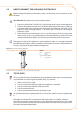
Before working on the electrical panel of the appliance, make sure that it is not con-
nected to the power supply.
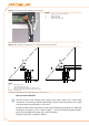
Cut a length of cable, long enough to allow it to be installed without kinking.1.
Having chosen one end of the length of cable, remove the sheath from a length of 2.
approximately 70-80 mm, taking care not to cut the shielding (metallic shield and/
or aluminium sheet and, if present, the bare connector in contact with the shield)
and the wires contained within.
If the cable is too thin to be held in place in the cable holder bracket (detail C in 3.
Figure 5.7 CAN BUS cable connection → 45), make it thicker by wrapping insulat-
ing tape around it on the sheath in the area adjacent to the stripped part (to an
approximate diameter of 12-13 mm).
Pull back the shielding in the sheathe; apply electrician’s tape to the end of the 4.
shielding as pulled back (detail A, Figure 5.7 CAN BUS cable connection → 45).
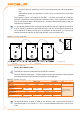
If the appliance is a 5. terminal node of the network connect the three coloured
wires to the orange connector, as shown in detail "A" of Figure 5.8 Electrical wir-
ing diagram → 46. Respect the correct indications L, H, GND provided in Table 5.2
CAN BUS cables type → 44, on the gure and on the diagram at the base of the
connector.
If the appliance is an 6. intermediate node repeat the operations from step 2 to step
5 for the other length of cable required (so to will have two cable lengths everyone
without the sheath). To interlace between they the threads with the same color
and to connect them to the orange connector, as shown in detail "B" of Figure 5.8
Electrical wiring diagram → 46.