
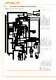
Technical data


44
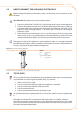
Terminal nodes are appliances or DDCs that are connected to one other element •
only.
Intermediate nodes are appliances or DDCs that are connected to two other •
elements.
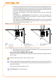
The diagram in Figure 5.6 Example of CAN BUS → 44 gives an example of a CAN BUS
network: 3 appliances are connected to each other and to 1 DDC. Appliance D and the
DDC (A) are terminal nodes, while appliances C and B are intermediate nodes as they are
connected to 2 elements.
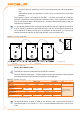
It is possible to place one DDC at any point of the CAN bus network: appliances and DDCs
may act equally as terminal or intermediate nodes. One DDC can control and monitor up
to 16 appliances. If there are more than 16 appliances on the network, it is necessary to
connect more than one DDC on the same network, up to a maximum of 3.
Figure 5.6 – Example of CAN BUS
Terminal nodes and intermediate nodes
LEGEND
A CCP or DDC
B-C-D Appliance
1-4 Terminal nodes
2-3 Intermediate nodes
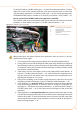
What is the CAN bus cable
The CAN bus cable must meet the {Honeywell SDS standard}.
Table 5.2 CAN BUS cables type → 44 gives details of some types of CAN bus cable, grouped
according to the maximum distance covered by each single type.
Table 5.2 – CAN BUS cables type
CABLE NAME SIGNAL / COLOR MAX LENGTH Note
Robur
Ordering Code O-CVO008
ROBUR NETBUS H= BLACK L= WHITE GND= BROWN 450 m
Honeywell SDS 1620
In all cases the fourth
conductor should not be
used
BELDEN 3086A
H= BLACK L= WHITE GND= BROWN 450 m
TURCK type 530
DeviceNet Mid Cable
TURCK type 5711 H= BLUE L= WHITE GND= BLACK 450 m
Honeywell SDS 2022
TURCK type 531 H= BLACK L= WHITE GND= BROWN 200 m
Example types of cables used to connect the CAN network.
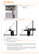
For overall distances to cover of ≤200 m and networks with a maximum of 6 nodes (a
typical example: up to 5 GAHP-A + 1 DDC) a simple shielded cable 3x0.75 mm may be
used.