
Technical data


Installation, user and maintenance manual – GAHP-A
39
5 ELECTRICAL SYSTEM INSTALLATION TECHNICIAN
This section illustrates the operations to perform for the correct electrical installation of
the appliance, and contains electrical diagrams that may be of use in the event of main-
tenance operations.
Installation of the appliance may only be carried out by rms that are qualied in accord-
ance with current legislation in the country of installation, i.e. by professionally qualied
personnel.
Installation that is incorrect or that does not comply with current legislation may cause
damage to people, animals or things; Robur S.p.A. is not responsible for any damage
caused by installation that is incorrect or that does not comply with current legislation.
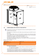
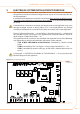
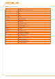
Figure 5.1 Electronic board S61 → 39 and Table 5.1 Electronic board S61 → 40 detail the
S61 controller’s inputs and outputs. The supplementary controller Mod10 is shown in
detail in Figure 5.2 Mod10 controller → 41.
The appliance and the system can be controlled and regulated in one of the following
ways depending on the type of installation and control system selected:
• TYPE A (NOT APPLICABLE at PRO Platform): controlled by Comfort Control
Panel.
• TYPE B: controlled by DDC (see Figure 5.3 Direct Digital Control (DDC) → 41).
• TYPE C: controlled by consent switch (e.g. on-o switch, ambient thermostat, tim-
er, etc.).
In Paragraph 5.1 ELECTRICAL DIAGRAMS OF THE APPLIANCE → 42 may be found the
Electrical diagrams of the appliance.
Figure 5.1 – Electronic board S61
SCH S61
LEGEND
See table below