
Technical data


Installation, user and maintenance manual – GAHP-A
35
This Table 4.2 Percentage of monoethylene glycol → 35 should be taken into account
for the sizing of the pipes and the circulation pump (for calculation of internal pressure
drops of the appliance, refer to the Table 2.1 GAHP-A LT technical data → 11 or Table 2.2
GAHP-A HT technical data → 12).
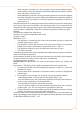
Nevertheless, it is advisable to consult the technical specications of the monoethylene
glycol used. If automatic loading systems are used, a seasonal check of the quantity of
glycol present in the plant is also necessary.
Table 4.2 – Percentage of monoethylene glycol
% of MONOETHYLENE GLYCOL 10 15 20 25 30 35 40
WATER FREEZING POINT TEMPERATURE -3°C -5°C -8°C -12°C -15°C -20°C -25°C
PERCENTAGE OF INCREASE IN PRESSURE DROPS -- 6% 8% 10% 12% 14% 16%
LOSS OF EFFICIENCY OF UNIT -- 0,5% 1% 2% 2,5% 3% 4%
Technical data for lling the hydraulic circuit
If the percentage of glycol is ≥ 30% (for ethylene glycol) or ≥ 20% (for propylene glycol):
then parameter 182 in menu 4 must be set to “1” (at the installer’s care).•
4.7 EXHAUSTING THE COMBUSTION PRODUCTS
The appliance is approved for the connection of the combustion product exhaust pi pes,
present on each single unit, to a ue linked directly to the outside.
Each single unit is provided with a connection of Ø 80 mm (equipped with a suitable
seal) located on the left side (see Figure 2.1 Size (Standard ventilation) → 14 or Figure 2.2
Size → 15) and outlet in a vertical position.
Each unit of the appliance is supplied complete with an exhaust air duct installation kit,
to be tted to the appliance by the hydraulic system installation technician.
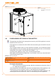
The exhaust air duct installation kit consists of (see Figure 4.4 Fume outlet → 36):
n. 1 exhaust air pipe Ø 80mm (length 300 mm) with terminal;•
n. 1 rain cover;•
n. 1 curve 90° Ø 80 mm.•
To assemble and t the external exhaust fumes installation kit, proceed as follows:
You will need: the appliance positioned in its installation site (refer to Figure 4.4 Fume
outlet → 36).
Fit the rain cover (C) on the curve 90° (A).1.
Fit the curve 90° (A) to the clamp on the left side of the appliance.2.
Fit the terminal/pipe assembly (B) to the curve (A).3.