
Technical data


Installation, user and maintenance manual – GAHP-A
33
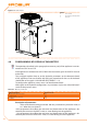
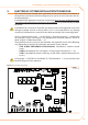
Figure 4.3 – Position of condensate discharge and manual reset fumes thermostat
LEGEND
A Condensate drain pipe
B
Condensate drain siphon
C Manual reset fumes thermostat
The condensate discharge to the sewer must be:
sized so as to discharge the maximum condensation ow (see Table 2.1 GAHP-A LT •
technical data → 11 or Table 2.2 GAHP-A HT technical data → 12 under the respec-
tive heading);
implemented with material capable of resisting a degree of acidity equal to 3 - 5 •
pH;
sized to ensure a slope of 10mm per metre of length; if this slope cannot be •
achieved, a condensate pump (available as an accessory) must be installed near to
the discharge - see Section 7 ACCESSORIES → 67);
implemented in such a way as to prevent the condensate icing in the expected •
operating conditions;
mixed, for example, with domestic euent (washing machine, dishwasher, etc.), •
usually of base pH, so as to form a buer solution before discharge into the sewer.
Do not discharge the condensate into the guttering, since it may ice and corrode the
materials normally used for gutters.
LOADING THE SIPHON
Proceed as follows to load the siphon:
Connect the condensate discharge pipe to a drain.1.
Pour 0.2 litres of water di rectly into the fumes discharge pipe and check that the 2.
siphon is full (detail B in Figure 4.3 Position of condensate discharge and manual
reset fumes thermostat → 33).
If the appliance is operated with the siphon empty, there is a risk of leaks of combusted
gas.