
Technical data


Installation, user and maintenance manual – GAHP-A
29
controlled” spread of water around the appliance and the consequent risk that a layer of
ice will form (with the danger of falls on the part of passing people).
The manufacturer may not be held responsible for any damage arising from the
failure to observe this warning.
Installation at ground level
If a horizontal support base is unavailable (see also "SUPPORTS and LEVELLING" below), it
is necessary to create a at level base in concrete which is larger than the dimensions of
the base of the appliance by at least 100-150 mm on each side.
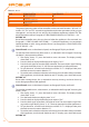
The dimensions of the appliance are given in Table 2.1 GAHP-A LT technical data → 11 or
Table 2.2 GAHP-A HT technical data → 12.
Provide a “containing” step and a suitable drainage channel for the water.
Installation on a terrace or roof
Position the appliance on a levelled at surface made of reproof material (see also "SUP-
PORTS and LEVELLING" below).
The structure of the building will have to support the weight of the appliance added to
the weight of the supporting base.
The weight of the appliance is given in Table 2.1 GAHP-A LT technical data → 11 or Table
2.2 GAHP-A HT technical data → 12.
Create a “containing” step and a suitable drainage channel for the water, providing a
gangway around the appliance for maintenance purposes.
Although the appliance produces vibrations of limited intensity, the use of antivibration
mounts (available as accessories, see Section 7 ACCESSORIES → 67) is strongly recom-
mended in such cases of installation on roofs or terraces in which resonance phenomena
may arise.
In addition, it is advisable to use exible connections (anti-vibration joints) between the
appliance and the hydraulic and gas supply pipes.
Avoid positioning the appliance directly above rest areas or other areas that require
quiet.
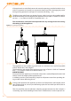
SUPPORTS and LEVELLING
The appliance must be correctly levelled by placing a level on the upper part of the
appliance.
If necessary, level the appliance with metal spacers, placing them appropriately in rela-
tion to the mounts; do not use wooden spacers as these degrade quickly.
CLEARANCES
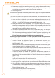
Position the appliance so as to maintain minimum clearances from combustible sur-
faces, walls or other appliances, as illustrated in Figure 4.2 Clearances → 30.
Minimum clearances are necessary in order to be able to carry out maintenance opera-
tions and to ensure the correct airow required for heat exchange with the nned coil.