
Technical data


24
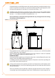
Disconnect the appliance from the power supply, putting the external disconnec-2.
tion switch in the OFF position (see GS in Figure 5.5 Electrical wiring diagram → 43)
provided in the appropriate panel by the installation technician.
Close the gas valve.3.
Do not leave the appliance connected to power and gas supply if it is expected to remain
inactive for a long period.
If you wish to disconnect the appliance during the winter, one of the following three
conditions must be met:
make sure that the hydraulic plant connected to the appliance contains an ad-1.
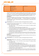
equate percentage of glycol antifreeze (see Paragraph 4.6 FILLING OF HYDRAULIC
CIRCUIT → 34 and Table 4.2 Percentage of monoethylene glycol → 35);
empty the hydraulic circuit completely: for this purpose the plant must be pro-2.
vided with water drainage points that are adequately equipped, sized and located,
to allow the water present in the circuit to drain away completely and to allow the
correct disposal of any glycol antifreeze present. For these operations, contact a
reputable hydraulic system installation technician;
activate the antifreeze function, which runs the circulation pumps and the appli-3.
ance under 6°C. To do this, contact your hydraulic system installation techni cian.
This function requires the appliance to be ALWAYS powered up (electricity and
gas) and power failures excluded.Otherwise the manufacturer declines all con-
tractual and extra-contractual liability for consequent damage.
Connecting the appliance before it is used again (to be carried out by the instal-
lation technician)
Before starting this procedure, the hydraulic system installation technician must:
ascertain whether the appliance requires any maintenance operations (con-•
tact your authorised Robur Technical Assistance Centre or consult Paragraph 6.2
MAINTENANCE → 63);
ll the hydraulic circuit if it has been emptied, carrying out the instructions given •
in Paragraph 4.6 FILLING OF HYDRAULIC CIRCUIT → 34;
if the hydraulic circuit has not been emptied, check that the water content of the •
plant is correct; if necessary, top up the circuit to at least the minimum quantity
(see Paragraph 4.6 FILLING OF HYDRAULIC CIRCUIT → 34);
if necessary add, to the water of the system (free of impurities), inhibited mo-•
noethylene glycol antifreeze in a quantity in proportion to the MINIMUM winter
temperature in the area of installation (see Table 4.2 Percentage of monoethylene
glycol → 35);
bring the plant to the correct pressure, making sure that the pressure of the water •
in the plant is not less than 1 bar and not over 2 bar;
You will need: the appliance disconnected from the electricity/gas supply
open the plant gas supply valve to the appliance and make sure that there is no 1.
smell of gas (indicating possible leaks);
If no smell of gas is detected, connect the appliance to the electricity supply mains 2.
via the external circuit breaker provided by the installation technician in the ap-
propriate panel (set the "GS" circuit breaker to the "ON" position, see Figure 5.5
Electrical wiring diagram → 43);
power up the CCP (if present) or DDC (if present);3.
check that the hydraulic circuit is charged;4.