
Technical data


20
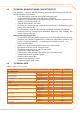
MENU MENU DESCRIPTION THE DISPLAY SHOWS
Menu 5 TECHNICAL ASSISTANCE CENTRE SETTINGS 5.
Menu 6 TECHNICAL ASSISTANCE CENTRE SETTINGS (MACHINE TYPE) 6.
Menu 7 VIEW DIGITAL IMPUTS 7.
Menu 8 (MENU NOT USED) 8.
E (EXIT MENU) E.
Menu list of electronic board
Menus 0, 1 and 7 are Viewing Menus: they only allow the information displayed to be
read, and not modied. Via menu 0 it is possible to view the appliance operating data as
detected by the board in real time; Menu 1 shows the parameters that characterise the
operation of the appliance and their current values.
Menu 7 pertains exclusively to Robur's authorized Technical Assistance Centres.
To view the information contained in these menus, proceed as illustrated in the para-
graph "How to acces the menus".
Menu 2 is an execution menu: it is used to reset the ame controller, reset errors and
manual defrosting control.
To perform these procedures, see Paragraph 3.3 RESET OPERATIONS AND MANUAL
DEFROSTING → 21.
Menu 3 is a settings menu: it allows the values displayed to be set. The correct values of
these parameters, for optimum performance of the appliance with the plant to be used
connected, have already been set during installation. In any case, to set new values for
the parameters, see Paragraph 4.8 PROGRAMMING OF HYDRAULIC PARAMETERS → 36.
Menus 4, 5, 6 and 7 exclusively concern the installation technician and Robur’s author-
ized Technical Assistance Centre.
Menu 8 may currently be selected, but not used.
Display and knob
The controller’s display can be viewed through the glass of the viewing aperture on the
front panel of the appliance.
Upon activation, all of the LEDs of the display light up for approximately three seconds,
and then the name of the board, S61, appears. After around 15 seconds after the appli-
ance powers up, the appliance starts running if the required consent is available.
During correct operation the display shows, alternately, the following information: outlet
water temperature, inlet water temperature, and the dierence between the two water
temperatures (see Table 3.2 Operating information → 20).
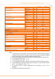
Table 3.2 – Operating information
OPERATING MODE: HEATING
PARAMETER THE DISPLAY SHOWS
Hot outlet water temperature 50.0
Hot inlet water temperature 40.0
Dierential temperature (outlet - inlet) 10.0
Example of data visualised on display: water temperature and dierential
If there are operating problems, the display shows, sequentially, the operating codes cor-
responding to the problem detected. A list of these codes with their description and the
procedure to follow to bring the appliance back to correct operation is provided in Para-
graph 8.1 MACHINE OPERATING CODES → 69.
The knob is used to display or set parameters, or to execute actions/commands (e.g.: a
function or reset), when permitted.
HOW TO ACCESS THE MENUS
To use the knob with the special key supplied with the appliance:•