
Technical data


Installation, user and maintenance manual – GAHP-A
19
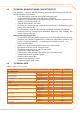
For the operating codes generated by the CCP/DDC, refer to the manuals supplied with
the unit.
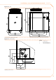
3.2 ONBOARD ELECTRONICS
The following descriptions refer to the S61 controller with rmware version 3.015.
The appliance is tted with an S61 microprocessor controller with Mod10 combustion
modulation controller mounted above it (see Figure 3.1 On-board controller → 19).
The S61 controller, in the electrical panel, controls the appliance and displays data, mes-
sages and operating codes.
Programming, control and monitoring of the appliance take place by interacting with
the display A and knob B shown in Figure 3.1 On-board controller → 19. La porta CAN
The CAN BUS port connects one or several appliances to the CCP (if present) or a DDC (if
present).
The Mod10 controller (see detail D in Figure 3.1 On-board controller → 19) is used for
combustion modulation.
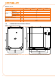
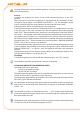
Figure 3.1 – On-board controller
S61 + Mod10
LEGEND
A 4 digit display
B
Knob
C CAN port
D Mod10 controller
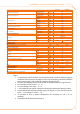
Description of menu of S61 controller
The parameters and settings of the appliance are grouped in the menus shown on the
controller’s display:
Table 3.1 – Menu of electronic board
MENU MENU DESCRIPTION THE DISPLAY SHOWS
Menu 0 VIEW DATA (TEMPERATURE, VOLTAGE, PUMP SPEED, ECC...) 0.
Menu 1 VIEW ALL PARAMETERS 1.
Menu 2 ENTER ACTIONS 2.
Menu 3 USER SETTINGS (THERMOSTATING, SET-POINT, T. DIFFERENTIAL) 3.
Menu 4 INSTALLATION TECHNICIAN SETTINGS 4.