
Technical data


8 Diagnostics
Installation, Use and Maintenance Manual – GA Line ACF Series
33
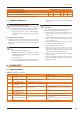
SCHEDULED MAINTENANCE OPERATIONS TO BE PERFORMED AT LEAST ONE EVERY TWO YEARS
Clean the electrodes of ignition and ame sensing √ √ √ √ √
Check that the condensate discharge is clean √ √ √
Replace the silicone gasket between the front plate and the exchanger √
*Only in case the analysis of combustion products is non-compliant
7.4 PERIODS OF INACTIVITY
Avoid emptying the water system
Emptying the system may cause damage due to corrosion of the
water pipes. Assure at least one of the two following conditions:
1. sucient anti-icing glycol (Paragraph 3.6p.21)
2. empty the system but ensure it is lled again in
compliance with the requirements of Paragraph
3.8p.22.
Prolonged periods of inactivity
▶
Should you foresee to leave the appliance inactive for a long
period of time, disconnect it from the electrical and gas
mains. These operations must be performed by Qualied
Personnel.
How to deactivate the appliance for long periods of
time
1. Switch the appliance o (6.2p.29).
2. Only when the appliance is completely o, power it
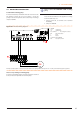
o with the main switch/disconnect switch (Detail
GS in Figure 4.2p.24).
3. Close the gas valve
4. If necessary, add water with glycol (if the appliance
is disconnected from the power and gas mains, the
active antifreeze protection is missing, Paragraph
3.5p.21).
How to reactivate the appliance after long periods
of inactivity
Before reactivating the appliance, the operator/mainte-
nance technician of the system must rst of all:
▶
Check whether any maintenance operations are re-
quired (contact the TAC; see Paragraphs 7.2 p. 32
and 7.3p.32).
▶
Check content and quality of the water in the system,
and if necessary top it up (Paragraphs 3.8 p. 22,
3.7p.21and 3.6p.21).
▶
Ensure the ue gas exhaust duct is not obstructed,
and that the condensate drain is clean.
After completing the above checks:
1. Open the gas cock and ensure there are no leaks;
should gas smell be noticed, close the gas cock
again, do not switch any electrical devices on and
request intervention by Skilled Personnel.
2. Power on with the main power supply switch (GS,
Figure 4.2p.24).
3. Switch on the appliance by means of the provided
control device (DDC, CCP/CCI or external request,
Paragraph 4.4p.25).
8 DIAGNOSTICS
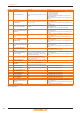
8.1 OPERATIVE CODES
Table 8.1 – Operative Codes ACF
CODES DESCRIPTION Warning (u) Error (E)
0
FAULT ON RESET CIRCUIT OF FLAME
CONTROL UNIT
NA
• Power cycle the appliance.
If the code persists, shows up again or in case of doubt, contact
the TAC.
1
GENERATOR LIMIT THERMOSTAT
TRIP
Contact authorised Technical Assistance
2 FLUE GAS THERMOSTAT TRIP Contact authorised Technical Assistance
3
COLD WATER ANTI-FREEZE THER-
MOSTAT TRIPPED
Reset is automatic when the triggering condition
ceases.
NA
4 INSUFFICIENT VENTILATION
Reset occurs automatically 20 minutes after the
code is generated.
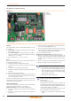
Reset may be performed from the DDC or from the S61 board
(menu 2, parameter 1).
If the code persists, shows up again or in case of doubt, contact
the TAC.
5
AMBIENT TEMPERATURE EXCEED-
ING OPERATIVE LIMITS
NA Reset is automatic when the triggering condition ceases.
6
AMBIENT TEMPERATURE LOWER
THAN OPERATIVE LIMITS
NA Reset is automatic when the triggering condition ceases.
7 GENERATOR TEMPERATURE HIGH
Reset is automatic when the triggering condition
ceases.
Reset may be performed from the DDC or from the S61 board
(menu 2, parameter 1).
If the code persists, shows up again or in case of doubt, contact
the TAC.
8 FLAME CONTROL UNIT ERROR NA Contact authorised Technical Assistance