
Technical data

4 Electrical installer
24
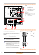
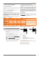
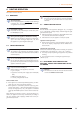
Figure 4.1 – GA-ACF Electrical Panel
4.3 ELECTRICAL POWER SUPPLY
Power supply line
Provide (by the installer) a protected single phase line (230 V 1-N
50 Hz) with:
▶
1 three-core cable type FG7(O)R 3Gx1,5;
▶
1 two-pole switch with two 5A type T fuses, (GS) or one 10A
magnetothermic breaker.
The switches must also provide disconnect capability,
with min contact opening 4 mm.
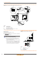
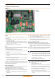
How to connect the power supply
To connect the three-pole power supply cable (Figure
4.2p.24):
1. Access the Electrical Board of the appliance accord-
ing to the Procedure 4.2p.23.
2. Connect the three lead-in wires to the terminal (TER)
in the electrical panel on the machine.
3. Provide the earth lead-in wire longer than live ones
(last to be torn in the event of accidental pulling).
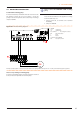
Figure 4.2 – Electrical wiring diagram
Example of connection of appliance to 230 V 1 N - 50 Hz electricity
supply
LEGEND
A CAN-BUS cable gland
B S61 electronic boards
C ME and TER terminal boards
D transformer 230/23 V AC
E ame controller
F circulation pump power supply and
control cable gland
G GA power supply cable gland
Terminals:
TER terminal box
L-(PE)-N phase/earth/neutral GA power supply
MA terminal box
N-(PE)-L neutral/earth/phase circulation pump
power supply
3-4 circulation pump enable
LEGEND
TER terminal
board
L phase
N neutral
Components NOT
SUPPLIED
GS general
switch