
Technical data


22
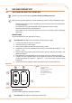
activate FAN ONLY mode;6.
activate HEATING mode;7.
in HEATING mode, close the gas supply line and check that the lockout led on the 8.
reset button "B" lights up after a few seconds (detail "3" - Figure 4.1 → 29);
now check that when you open teh gas cock and press reset button "B", the lockout 9.
led goes out and the generator starts up again;
If the appliance behaves in any other way than specified in the procedures in Paragraph
4.1 SWITCHING ON AND SWITCHING OFF → 29 or exhibits any anomalous behaviour,
this indicates a possible wiring error. Check the connections and if the anomaly persists,
contact your local TAC or Robur Spa Service (tel. +39.035.888.111).
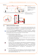
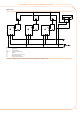
CONTROLLING MULTIPLE APPLIANCES WITH A SINGLE EXTERNAL ENABLE SIGNAL
Terminals "Z9-Z9" enable you to control multiple generators with a single external enable
signal (e.g.: analogue thermostatic programmer, clock, etc.).
There are three possible control options as shown in Figures 3.12 → 25, 3.13 → 26 and
3.14 → 27:
control of multiple appliances with a single programmer and multiple room •
thermostats;
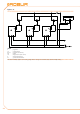
control of multiple appliances with a single programmer and a single room ther-•
mostats (with multiple relays);
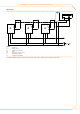
control of multiple appliances with a single programmer and a single room ther-•
mostats (with a single relay).
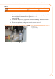
3.5 SETTING THE GAS VALVE
For correct operation of series B15 generators, the gas valve must be set to the values
given in Table 3.5 → 23. The appliance is shipped with the gas valve already set.
If further adjustment should be necessary, proceed as explained below (see Figure
3.10 → 23).
The adjustment must be done by professionally qualified personnel. ROBUR S.p.A. has
a network of Assistance Centres which can be contacted via your reseller, area agent, or
by phoning ROBUR S.p.A. Customer Assistance tel. +39.035.888.111.
You will need: the appliance connected to the power/gas supply. Necessary equip-
ment and materials.
Connect a pressure gauge to pressure fitting "B", after having slackened off the seal 1.
screw.
If using a differential gauge, connect gas valve fitting "B" to the gauge’s + (positive)
terminal.
Turn on the appliance and wait for the flame to reach a steady state (around 2 2.
minutes).
Operation with hatch open: remove its cap with a screwdriver and adjust offset 3.
adjuster screw "A" (you will need a 4 mm allen key) to the nominal value given in
3.5 → 23.