
Technical data


Installation, user and maintenance manual – Series B15 Generators
21
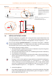
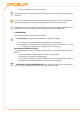
Figure 3.9
Installation with supporting bracket provided by installer.
LEGEND
S supporting plate
P wall-mounted plate (and counterplate)
a generator base mounting hole spacing
c generator rear mounting hole spacing
b generator base/rear support plane line
of intersection
v generator mounting bolts (*)
D detail of "b-c"
* use (n. 4):
spring washer 6.4x12.5 UNI 6592-69-R4O galvanised
washer D.6 UNI 8842 A6 galvanised
bolts UNI EN 24017-M6x20-8.8 galvanised
a
b
176 mm
D
S
v
v
b
c
12 mm
D
MIN 300 mm
340 mm
90 mm
P
430 mm
a
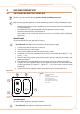
3.4 INSTALLING THE WALL PANEL
Series B15 appliances are supplied with a wall panel with: summer/winter button and
reset button with lockout led (Figure 4.1 → 29). The panel should be installed on the wall
in an appropriate position. It connects to the appliance as shown in Figure 3.11 → 24.
This must be done by a qualified technician, as instructed in Paragraph 3.1 GENERAL
INSTALLATION INSTRUCTIONS → 13 . Make sure that the cables are not live when making
the connection. Each wire must have at least a 1 mm cross section.
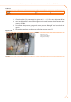
To install the wall panel, proceed as follows:
after having found a suitable location (at most 100 metres away from the genera-1.
tor itself), install it with the expansion bolts;
then route the cable (FROH 8x1 mm2.
2
) of a suitable length (maximum 100 metres);
shut off power to the appliance;3.
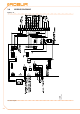
open the hatch on the appliance and connect the cable to the terminal block, as 4.
shown in the installation wiring diagram, Figure 3.11 → 24 (see connection details
"E/I" and "Reset");
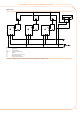
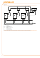
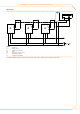
Terminals "Z9-Z9" on the appliance’s terminal block are intended for hooking up a
room thermostat (see connection detail "T.A" - in the Figure 3.11 → 24). Terminals
"Z9-Z9" enable you to control multiple generators with a single external enable
signal (e.g.: analogue thermostatic programmer, clock, etc.) as shown in the con-
nection examples in Figure 3.12 → 25, Figure 3.13 → 26 and Figure 3.14 → 27.
restore the appliance.5.
Now check the operation of the appliance to ensure the connections have been
made correctly. With reference to the procedures given in Paragraph 4.1 SWITCH-
ING ON AND SWITCHING OFF → 29: