
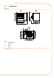
Technical data


20
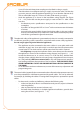
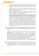
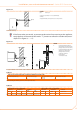
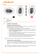
Figure 3.8
Wall terminal position.
LEGEND
IN combustion air intake
OUT fumes exhaust
A recommended position (OK)
B admitted position (OK)
C NOT admitted position (NO)
IN
OUT
A
IN
OUT
B
IN
OUT
C
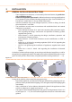
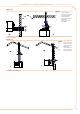
3.3 BRACKET INSTALLATION
USING ROBUR SUPPORTING BRACKETS
ROBUR S.p.A. provides easy to install mounting brackets as accessory equipment for the
series B15 generator [accessory code: O-STF019].
To install the appliance using the Robur (O-STF019) mounting bracket:
install the bracket to the appliance as explained in the instructions supplied with 1.
the O-STF019 mounting bracket itself;
follow the instructions given in Paragraph 3.1 GENERAL INSTALLATION INSTRUC-2.
TIONS → 13 and Figure 3.2 → 15;
drill n. 4 holes into the wall (through its entire thickness) in line with the 4 holes in 3.
the wall plate supplied with the Robur bracket;
secure the generator’s mounting bracket to the wall using the counterplate sup-4.
plied with the Robur bracket: secure the counterplate (located on the outside of
the wall) to the wall plate (on the inside of the wall) with 4 M10 bolts.
Observe the warnings given in the Robur O-STF019 bracket’s assembly instructions.
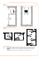
USING SHELVES (not supplied by Robur)
If he opts not to use Robur mounting accessories, the installer must not only observe the
instructions given in Paragraph 3.1 GENERAL INSTALLATION INSTRUCTIONS → 13 and
Figure 3.2 → 15, but must also employ a shelf which satisfies the specifications of Figure
3.9 → 21.
The shelf must be sufficiently robust for its intended use and able to support the weight
of the appliance (see Table 2.1 Technical data. → 10) plus its own.