
Technical data


Installation, user and maintenance manual – Series B15 Generators
17
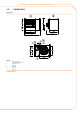
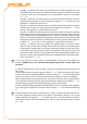
Figure 3.4
horizontal tube slope.
LEGEND
p(%) tube slope *
* slope to be provided: -2% or -3% (downwards).
example:
slope (downwards) of 2 cm per metre or 3 cm per metre
p(%)
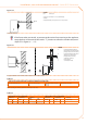
If the fumes tubes are vertical, to prevent condensation from returning to the appliance,
equip the base of the vertical tube with a "T" junction to collect the condensate (see ex-
ample "B" in Figure 3.5 → 17).
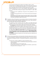
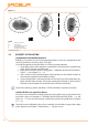
Figure 3.5
B23 type installations: with wall-mounted exhaust and roof-mounted exhaust.
LEGEND
A type B23 installation with hori-
zontal exhaust (or wall-mounted)
[B15 generator: seen from above]
B type B23 installation with vertical
exhaust (or roof-mounted)
[B15 generator: side view]
1 combustion air intake
2 fumes exhaust
3 condensation outlet
1
2
A
3
2
B
B15
B15
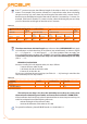
Table 3.1
DATA FOR CALCULATING THE AIR/FUMES SYSTEM WITH COMMERCIALLY AVAILABLE TUBES
Fumes outlet temperature [°C] Fumes mass flow rate [kg/h]
CO
2
content of fumes [%] (with
G20 gas)
Admitted pressure drop [Pa]
175 25,9 9,2 ÷ 9,4 60
Data for calculating the air/fumes system with commercially available tubes.
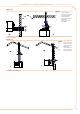
Table 3.2
PRESSURE DROP OF DIA. 80 COMPONENTS PRESSURE DROP OF DIA. 100 COMPONENTS
tube [Pa/m] 90° bend [Pa] coaxial [Pa] tube [Pa/m] 90° bend [Pa] coaxial [Pa]
fumes air fumes air
wall
O-SCR007
roof
O-SCR008
fumes air fumes air roof O-SCR009
0,7 0,4 1,0 0,9 1,6 2,0 0,2 0,2 0,35 0,25 1,0
Dati per il calcolo del sistema aria/fumi con condotti Ø 80 o Ø 100 forniti da Robur Spa.