
Technical data


14
A cut-off valve and three-piece coupling must be fitted on the gas supply.•
Check that there is an adequate mains gas supply. In particular: make sure that the •
gas mains pressure, with the appliance operating, is set to 20 mbar (204 mm H
2
O)
with an admissible range of 17 mbar to 25 mbar (G20 natural gas supply).
Hook the appliance up as shown in the installation wiring diagram (see Figure •
3.11 → 24), and make sure the power supply is rated at 230 V 1N - 50Hz. Make
sure that:
the electricity mains specifications correspond to the specifications on the •
nameplate;
the cable is of the type H05 VVF 3x1.5 mm•
2
with a maximum external diameter
of 8.4mm;
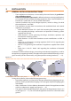
ensure that the ground cable is longer than the live cables. In this way it will be •
the last wire to be pulled away if the mains cable should accidentally be pulled,
and will thus guarantee the ground connection.
The electrical safety of the appliance is guaranteed only when it is correctly connected to
an efficient grounding system, executed in accordance with current safety regulations.
Do not use gas pipes to ground electrical appliances.
The appliance must be connected to the mains cable via a two-pole switch with •
minimum air gap 3 mm. A two-pole switch is one which opens both the phase and the
neutral contacts. Thus both contacts will be open when the switch is opened.
• It is obligatory to equip the installation with a room thermostat connected to
the appliance as shown in the installation wiring diagram (see Figure 3.11 → 24).
Locate the thermostat (or its sensor) around 1.5 m off the floor, shielded from
draughts, direct sunlight, direct heat sources (lamps, the appliance’s hot air output,
etc.) and preferably NOT on an external wall, as this will compromise its tempera-
ture reading and hence the operation of the installation. THIS PREVENTS UNDE-
SIRABLE OPERATING CYCLES AND ENSURES OPTIMAL HEATING COMFORT IN
THE ROOM.
As an alternative to the room thermostat, use one of the accessory adjustment and •
programming units.
The control cables (especially those connected to the wall panel and temperature sensors)
must be protected from interference generated by power cables. This can be achieved,
for example, by shielding the cables or routing them through ducts separate from power
cables.
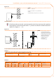
For best results, comfort and efficiency, observe the following rules:•
make sure that the air flow is not directed towards persons (adjust its direction •
with the grille fins)
take any obstacles into account (columns, etc.).•
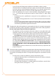
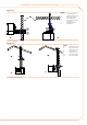
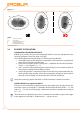
fro better heat distribution, in multiple appliance installations, provide alter-•
nating hot air flows (see Figure 3.3 → 15).