Installation, user and maintenance manual Series B15 Generators Gas fired unit heaters for heating medium areas Methane gas powered
Revision: A Code: D-LBR595 This manual has been drawn up and printed by Robur S.p.A.; whole or partial reproduction of this manual is prohibited. The original is filed at Robur S.p.A. Any use of this manual other than for personal consultation must be previously authorised by Robur S.p.A. The rights of those who have legitimately filed the registered trademarks contained within this publication are not affected. With the aim of continuously improving the quality of its products, Robur S.p.A.
Installation, user and maintenance manual – Series B15 Generators Index of contents 1 PREFACE ������������������������������������������������������������������������������������������������������������5 2 OVERVIEW AND TECHNICAL CHARACTERISTICS �����������������������������������������7 2.1 WARNINGS ��������������������������������������������������������������������������������������������������������������������������������������������������������������������������������������� 7 2.
Installation, user and maintenance manual – Series B15 Generators 1 PREFACE The present "Installation, user and maintenance manual" is intended for anyone who is to install or operate Robur series B15 hot air generators. In particular, the booklet is intended for the plumber who will install the generator, the electrician who will connect it to the mains power supply and the final user who will control it during everyday operation.
Installation, user and maintenance manual – Series B15 Generators 2 OVERVIEW AND TECHNICAL CHARACTERISTICS This section contains general instructions regarding the installation and operation of series B15 generators, and a brief section about the operation of generators, their construction and technical data. 2.1 WARNINGS This manual constitutes an integral and essential part of the product and must be delivered to the user together with the appliance.
• • • • • t he gas supply seals, both internal and external; the gas flow rate setting as required by the generator’s power rating; the gas supplied to the appliance is of the type for which it is designed; the gas supply pressure in relation to the admitted range specified on the nameplate; the gas supply system is correctly rated for the capacity required by the appliance, and that it is equipped with all safety and control devices prescribed by current regulations.
Installation, user and maintenance manual – Series B15 Generators • • • • • • • pre-mix burner in stainless steel. high head blower. cylindrical combustion chamber in stainless steel. heat exchangers in corrugated stainless steel with a very large exchange surface. external panelling in steel with epoxy powder enamel finish. high capacity axial fan.
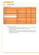
2.4 TECHNICAL DATA Table 2.1 – Technical data. TECHNICAL CHARACTERISTICS appliance category appliance type gas thermal capacity thermal power gas consumption (1) efficiency gas supply pressure gas fitting dia. fumes/combustion air fitting dia. electrical power electrical power absorption fuse operating temperature (2) air flow (3) thermal differential air throw (4) sound level at 6 m sound level at 6 m weight Technical data.
Installation, user and maintenance manual – Series B15 Generators 2.5 DIMENSIONS Figure 2.2 LEGEND 1 2 3 4 A B C fumes outlet fitting combustion air intake fitting power cable inlet gas fitting front view side view rear view Series B15 dimensions.
Installation, user and maintenance manual – Series B15 Generators 3 INSTALLATION 3.1 GENERAL INSTALLATION INSTRUCTIONS T he installation must be done, as instructed by the manufacturer, by professionally qualified personnel. • Professionally qualified personnel is defined as those possessing specific technical competence in the residential heating equipment sector. Contact ROBUR S.p.A. Presales (tel. +39.035.888.111) for any further information.
• • • cut-off valve and three-piece coupling must be fitted on the gas supply. A Check that there is an adequate mains gas supply. In particular: make sure that the gas mains pressure, with the appliance operating, is set to 20 mbar (204 mm H2O) with an admissible range of 17 mbar to 25 mbar (G20 natural gas supply). Hook the appliance up as shown in the installation wiring diagram (see Figure 3.11 → 24), and make sure the power supply is rated at 230 V 1N - 50Hz.
Installation, user and maintenance manual – Series B15 Generators Figure 3.2 Min 400 300 350 Min 200 A A Min 2,5 m 2,2 ÷ Max 3,0 3,5 [m]m (min/max) Clearances: minimum clearance required for installation. Figure 3.3 Example of generator positioning. 3.2 SIZING AND INSTALLING THE COMBUSTION AIR/FUMES EXHAUST TUBES Series B15 hot air generators can be installed in one of the following ways.
• • • • • T ype B23 installation: this type has the combustion air intake inside the room and the fumes exhaust outdoors via a dedicated tube, which may be either horizontal or vertical. In this case, the appliance is not sealed off from the room (see Figure 3.5 → 17). Type C13 installation: The fumes exhaust and the air intake are routed in coaxial or separate horizontal tubes (or wall-mounted, see Figure 3.6 → 19). In this case, the appliance is sealed off from the room.
Installation, user and maintenance manual – Series B15 Generators Figure 3.4 LEGEND p(%) t ube slope * * slope to be provided: -2% or -3% (downwards). example: slope (downwards) of 2 cm per metre or 3 cm per metre p(%) horizontal tube slope. If the fumes tubes are vertical, to prevent condensation from returning to the appliance, equip the base of the vertical tube with a "T" junction to collect the condensate (see example "B" in Figure 3.5 → 17). Figure 3.
Each "T" junction increases the effective length of the tube to which it is mounted by 3 metres. For example, if the junction is fitted to a 2 metre fumes tube, when calculating the pressure drop you must deem the total length of the tube to be 5 metres. Each 5° bend increases the effective length of the tube to which it is mounted by 1.2 metres. For example, if the bend is fitted to a 2 metre air tube, when calculating the pressure drop you must deem the total length of the tube to be 3.2 metres. Table 3.
Installation, user and maintenance manual – Series B15 Generators Figure 3.6 LEGEND C13 V1 E1 E2 A F C 13 type installations g enerator, seen from above e xample with separate wall-mounted ducts e xample with coaxial wallmounted duct c ombustion air intake f umes exhaust C13 type installations. Figure 3.7 LEGEND V1 V2 A F S.
Figure 3.8 B C A IN LEGEND IN OUT A B C OUT OUT IN IN OUT combustion air intake fumes exhaust recommended position (OK) admitted position (OK) NOT admitted position (NO) Wall terminal position. 3.3 BRACKET INSTALLATION USING ROBUR SUPPORTING BRACKETS ROBUR S.p.A. provides easy to install mounting brackets as accessory equipment for the series B15 generator [accessory code: O-STF019]. To install the appliance using the Robur (O-STF019) mounting bracket: 1.
Installation, user and maintenance manual – Series B15 Generators Figure 3.9 LEGEND S supporting plate P w all-mounted plate (and counterplate) a g enerator base mounting hole spacing c g enerator rear mounting hole spacing b g enerator base/rear support plane line of intersection v g enerator mounting bolts (*) D d etail of "b-c" 176 mm D v a b S v * use (n. 4): spring washer 6.4x12.5 UNI 6592-69-R4O galvanised washer D.6 UNI 8842 A6 galvanised bolts UNI EN 24017-M6x20-8.
6. a ctivate FAN ONLY mode; 7. activate HEATING mode; 8. in HEATING mode, close the gas supply line and check that the lockout led on the reset button "B" lights up after a few seconds (detail "3" - Figure 4.1 → 29); 9. now check that when you open teh gas cock and press reset button "B", the lockout led goes out and the generator starts up again; If the appliance behaves in any other way than specified in the procedures in Paragraph 4.
Installation, user and maintenance manual – Series B15 Generators Table 3.5 OFFSETS OFFSET nominal Offsets. [mbar] -0,1 [Pa] -10 1. C heck that the CO2 percentage is as given in 3.1 → 17. If it is not, adjust the offset again until the CO2 percentage is as given in 3.1 → 17. 2. Turn the appliance off and back on again two or three times to check that the new setting is stable. 3. Disconnect the pressure gauge and screw pressure fitting "B" seal screw back in again. 4.
3.6 WIRING DIAGRAMS LEGEND vedi disegno Figure 3.11 Installation diagram.
Installation, user and maintenance manual – Series B15 Generators Figure 3.12 LEGEND P TA RL1-2-3 GR L-N A Z9 programmer room thermostat programmed control relay ground single-phase line (230 V - 50 Hz) wall-mounted generator generator internal terminals Installation of multiple appliances with a single programmer and multiple room thermostats.
Figure 3.13 LEGEND P TA RL1-2-3 GR L-N A Z9 programmer room thermostat programmed control relay ground single-phase line (230 V - 50 Hz) wall-mounted generator generator internal terminals Installation of multiple appliances with a single programmer and a single room thermostat (solution with multiple relays).
Installation, user and maintenance manual – Series B15 Generators Figure 3.14 LEGEND P TA RL GR L-N A Z9 programmer room thermostat programmed control relay ground single-phase line (230 V - 50 Hz) wall-mounted generator generator internal terminals Installation of multiple appliances with a single programmer and a single room thermostat (solution with a single relay).
Installation, user and maintenance manual – Series B15 Generators 4 USE AND OPERATION 4.1 SWITCHING ON AND SWITCHING OFF The first start up must be done by professionally qualified personnel.
• Set the room thermostat to its minimum. The burner will go out, whereas the fan will continue running so long as the appliance is still warm. Do not switch off the appliance by shutting off its power supply as this can severely damage it by stopping the fan and tripping the limit thermostat (automatic reset). The limit thermostat ONLY trips during malfunctions. Before resetting it, troubleshoot the problem (in this case, overheating). If it trips frequently, contact ROBUR TAC.
Installation, user and maintenance manual – Series B15 Generators 5 SERVICE AND ASSISTANCE 5.1 MALFUNCTIONS Before taking any particular measures, always check that: • the power supply is present: 230 V ± 10% 50 Hz with an effective ground plant; • the gas supply is present; • the gas pressure and flow rate must be in the range specified by the manufacturer. A lower pressure than that indicated by the manufacturer corresponds to an insufficient gas supply.
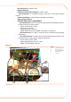
You will need: generator powered off, with master power switch set to "OFF" and gas valve set to "CLOSED". 1. 2. 3. 4. 5. 6. 7. 8. 9. 10. 11. 12. 13. 14. pen the generator’s hatch. O Undo the hexagonal ring nut connecting the gas pipe to the nozzle mount fitting. Move the gas pipe aside and remove the nozzle. Undo the four bolts securing the blower screw. Remove the deflector and its gasket.
Installation, user and maintenance manual – Series B15 Generators 33
Robur Mission Robur Spa tecnologie avanzate per la climatizzazione Via Parigi 4/6 24040 Verdellino/Zingonia (Bg) Italy T +39 035 888111 F +39 035 884165 www.robur.it robur@robur.it Revision: A Code: D-LBR595 10 MED SDC 005 19/11/2010 Robur is dedicated to dynamic progression in research, development and promotion of safe, environmentally-friendly, energy-efficiency products, through the commitment and caring of its employees and partners.