
Data Sheet


ADXL335
Rev. B | Page 3 of 16
SPECIFICATIONS
T
A
= 25°C, V
S
= 3 V, C
X
= C
Y
= C
Z
= 0.1 µF, acceleration = 0 g, unless otherwise noted. All minimum and maximum specifications are
guaranteed. Typical specifications are not guaranteed.
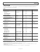
Table 1.
Parameter Conditions Min Typ Max Unit
SENSOR INPUT Each axis
Measurement Range ±3 ±3.6
g
Nonlinearity % of full scale ±0.3 %
Package Alignment Error ±1 Degrees
Interaxis Alignment Error ±0.1 Degrees
Cross-Axis Sensitivity
1
±1 %
SENSITIVITY (RATIOMETRIC)
2
Each axis
Sensitivity at X
OUT
, Y
OUT
, Z
OUT
V
S
= 3 V 270 300 330 mV/g
Sensitivity Change Due to Temperature
3
V
S
= 3 V ±0.01 %/°C
ZERO g BIAS LEVEL (RATIOMETRIC)
0 g Voltage at X
OUT
, Y
OUT
V
S
= 3 V 1.35 1.5 1.65 V
0 g Voltage at Z
OUT
V
S
= 3 V 1.2 1.5 1.8 V
0 g Offset vs. Temperature ±1 mg/°C
NOISE PERFORMANCE
Noise Density X
OUT
, Y
OUT
150 µg/√Hz rms
Noise Density Z
OUT
300 µg/√Hz rms
FREQUENCY RESPONSE
4
Bandwidth X
OUT
, Y
OUT
5
No external filter 1600 Hz
Bandwidth Z
OUT
5
No external filter 550 Hz
R
FILT
Tolerance 32 ± 15% kΩ
Sensor Resonant Frequency 5.5 kHz
SELF-TEST
6
Logic Input Low +0.6 V
Logic Input High +2.4 V
ST Actuation Current +60 A
Output Change at X
OUT
Self-Test 0 to Self-Test 1 −150 −325 −600 mV
Output Change at Y
OUT
Self-Test 0 to Self-Test 1 +150 +325 +600 mV
Output Change at Z
OUT
Self-Test 0 to Self-Test 1 +150 +550 +1000 mV
OUTPUT AMPLIFIER
Output Swing Low No load 0.1 V
Output Swing High No load 2.8 V
POWER SUPPLY
Operating Voltage Range 1.8 3.6 V
Supply Current V
S
= 3 V 350 A
Turn-On Time
7
No external filter 1 ms
TEMPERATURE
Operating Temperature Range −40 +85 °C
1
Defined as coupling between any two axes.
2
Sensitivity is essentially ratiometric to V
S
.
3
Defined as the output change from ambient-to-maximum temperature or ambient-to-minimum temperature.
4
Actual frequency response controlled by user-supplied external filter capacitors (C
X
, C
Y
, C
Z
).
5
Bandwidth with external capacitors = 1/(2 × π × 32 kΩ × C). For C
X
, C
Y
= 0.003 µF, bandwidth = 1.6 kHz. For C
Z
= 0.01 µF, bandwidth = 500 Hz. For C
X
, C
Y
, C
Z
= 10 µF,
bandwidth = 0.5 Hz.
6
Self-test response changes cubically with V
S
.
7
Turn-on time is dependent on C
X
, C
Y
, C
Z
and is approximately 160 × C
X
or C
Y
or C
Z
+ 1 ms, where C
X
, C
Y
, C
Z
are in microfarads (µF).