i ® Toby Tire Robot Operating Manual ™ Version 6.
ii Toby Tire Operating Manual Congratulations on your purchase of a ROBOTRONICS, Inc. robot. Your robot has been carefully constructed of the highest quality components. Its design is the result of years of experience building robots. You will find it an extremely effective spokesman for your organization. It is built for ease of operation, maintenance and repair. It is built so that you can easily expand its functions making its usefulness grow as your needs grow. Please read this manual carefully.
Contents Contents Warranty Information .............................................................................................. 1 PART 1 General Operating Instructions .......................................... 3 Chapter 1 Getting Started ......................................................................3 Operating Hints ..................................................................................................... 3 Setup and How To Operate The Robot.......................................
iv Contents PART 3 Assembly & Disassembly................................................35 Chapter 11 Assembly & Disassembly..................................................35 PART 4 Maintenance................................................................................ 36 Chapter 12 Maintenance ......................................................................36 Regular Maintenance Checklist .......................................................................... 36 Recommended Tool Kit.....
Warranty Information and Getting Help 1 Limited Warranty All robots and accessories have a limited 6-month warranty, which covers all parts and labor. This period covers the normal burn-in for electronic components. Experience has shown that this warranty period catches most component defects and other possible flaws. If you have a problem, we are anxious to help. Our desire is to be certain you receive a quality product and excellent service.
2 Warranty Information and Getting Help • Upon the receipt of your product, save all packing materials to return the product if needed. • If you must return a part or the robot for repair, pack it carefully and send it prepaid according to instructions. You must obtain a return authorization number from the service department before shipping the robot or a part to the factory. • Parts of the robot are best sent by a carrier such as UPS, Fed. Ex. or U.S.
Operating Hints 3 Part 1 General Operating Instructions CHAPTER 1 Getting Started OPERATING HINTS ROBOTRONICS, Inc. robots are a unique and exciting tool in the hands of a skilled and trained operator. The operator provides much of the excitement the robot conveys. The selection and training of the operator should be done carefully, so as to provide a person with good judgment and an outgoing personality. The operator is the single most important feature that the robot has.
4 Setup and How to Operate the Robot SETUP AND HOW TO OPERATE THE ROBOT Step # 1 Read and study this manual completely before operating the robot. Step # 2 Charge the batteries Be certain that the robot battery and radio control transmitter battery are fully charged before operating the robot. Install the robot battery. Open the rear door or trunk to gain access. 1. Put the robot battery in the compartment in the back. 2. Connect the robot battery connector to the robot connector.
Setup and How to Operate the Robot 5 Step # 9 Charge the batteries again Connect the Robot battery to the charger and bring it back to a full charge before leaving the robot. This battery should not be left with a partial charge. The transmitter battery should be charged if it is low. • All of the major functions of the robot each have a section in the manual with more details and diagrams. Refer to these for more in depth information.
6 Transporting the Robot TRANSPORTING THE ROBOT Before transporting the robot, remove the robot battery from the robot. The vehicle that you use to transport the robot should have adequate shock absorption. Vans and cars used for passengers would be the best. Transporting the robot in a trailer is not recommended because trailers typically do not have the same level of shock absorption as a car or van.
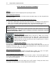
Subsystems 7 Part 2 Subsystems of the Robot Functionally, the robot is made up of the following basic subsystems: A. Radio Control System B. Voice System C. Cassette Tape Player D. Siren E. Robot Battery Systems F. Drive Motors G. Eyelids and Eyes Left and Right The systems block diagram found in the Appendix shows how the various subsystems and their components are interrelated. Following are explanations of each subsystem, some operating instructions, and trouble shooting hints where appropriate.
8 Radio Control System CHAPTER 2 Radio Control System The Radio Control System consists of the control transmitter unit held by the operator and the receiver with its associated components in the robot. The Radio Control Transmitter converts movements of the control sticks and switches into a coded radio signal, which is transmitted by radio to the Radio Control Receiver within the robot. The signal is received and then decoded by the micro-controller, which is on the main circuit board in the vehicle.
Radio Control Diagram 9 RADIO CONTROL TRANSMITTER (Hi-Tec) 1 12 2 14 15 16 13 3 11 10 9 4 8 5 6 7
10 Radio Control Functions RC TRANSMITTER CONTROLS Note: The following information on the transmitter controls includes information for a variety of similar robots. 1. Telescopic Transmitter Aerial. 2. Transmitter Battery Voltage Meter (Expand Scale Voltmeter) 3. Right control StickUp and Down – Robot drive motors, forward and reverse. Right and Left – Robot drive motors steering. Left and right turns. 4. Forward/Reverse Trim lever for right control stick. Normal = Center.
11 Top Switch Functions 12. Tape player 13. Blink eyes 14. Dance and Handshake 15. Unused 16.
12 RC Transmitter Battery THE NICKEL METAL HYDRIDE (NI-MH) RC TRANSMITTER BATTERY The NI-MH RC transmitter battery will last about 5-6 hours on a full charge. Charge the battery for 16 hours. A charge jack is provided on the transmitter for recharging its internal batteries. This round jack is located on the right side of the radio control.
Adapter and 110 V Supply 13 Adapter for Charging an Extra NI-MH RC Transmitter Battery If you have an extra NI-MH RC battery, you can charge this outside the RC. You may want to do this while you are using the robot or if you need to charge both batteries at the same time. The adapter needed to do this is in the control case or it is on your charger. It has a white connector on one side and a connection on the other end that will go directly to your battery. The charging time is still 16 hours.
14 Voice System CHAPTER 3 Voice System The Voice System consists of two separate communication links. One link transmits the operator's voice to the robot. When you speak into the headset mic, this audio goes to a transmitter on your belt. This audio is transmitted to a receiver in the robot. The audio signal then goes from the receiver through a mixing circuit on the main board. It is then is fed into the amplifier which amplifies the signal through the robot's speakers.
Voice System 15 How to Operate the Operator’s Transmitter 1. Open the battery door. 2. Use a 9 Volt alkaline battery and insert it according to the diagram inside the battery compartment. 3. Place the headset on your head and adjust the microphone to approximately 1 inch from your mouth. 4. Plug the round connector from the headset into the top of the transmitter. 5. Move slide switches to the "ON" position. 6. On the UB-10 there is a volume adjust on the unit.
16 Voice System How to Operate the Receiver (in Robot) There are two adjustments on the receiver. The volume is on the back of the receiver, which you may set to the desired volume. On the UHF UB-10 you can change the volume on your belt transmitter on the fly. The other adjustment is the sensitivity. This is factory preset to maximum sensitivity. This effects how sensitive the receiver is to the transmitter signal. Typically you would never need to adjust this.
Voice System 17 How to Operate the 151 Transmitter (in Robot) No adjustment is needed. The switches will be preset to on at the factory. It receives its power from the robot. No 9 Volt battery is needed. Function of the LED When the robot is turned on, this light flashes and then goes out. This indicates that the transmitter is getting power. How to Operate the 151 Receiver (Operator) 1. Remove the battery door. 2.
18 Voice System Troubleshooting ! Warnings 1. Do not unplug or plug in the DC power plug on the robot receiver with the robot power on. If the power is left on, the plug will short out and could damage the receiver. The fuse in line on the power wire that is plugged into this receiver may blow. This fuse is a round black fuse holder. If this fuse is not blown but no RX power light is on, check the audio fuse on the main fuse block in the electronics box. 2.
Voice System Troubleshooting Problem Cause 19 Solution Voice System Always do the following first: 1. Replace the 9 Volt batteries with new ones. USE ALKALINE! 2. Bend the battery contact out for better contact with the post of the 9 Volt battery. 3. Check power and audio switches, and lights on all voice units. 4. Check plug to and from the voices for proper connection. 5. Check if the transmit (TX) lights are coming on. Operator cannot talk 1. Low Battery. LED on steady or no LED flash. 2.
Moving Mouth 20 MOVING MOUTH FunctionThe moving mouth is a feature where the mouth moves as the operator speaks through the robot. The amount of the movement is effected by the level of volume of the voice. This level is effected by the Receiver volume level and the position of the headset microphone to the operator's mouth. The sensitivity is set based on a typical voice volume and the headset microphone being about 1 inch from the operator’s mouth.
Operator Voice Units 21 Operator’s Voice Transmitter and Receiver 3.5mm Headphones Plug Mic Plug - 3.
22 Cassette Tape Player CHAPTER 4 Cassette Tape System The cassette tape system is located inside the robot on the metal electronics box. The system is activated by remote control from the remote control box. (Additional instructions are on the next page.) How to Play A Cassette Tape 1. 2. 3. 4. 5. Insert a regular type cassette tape into the player. Depress the play button on the cassette player. Move the radio tape select switch to the tape position. Activate the tape from the control box.
Cassette Tape Player Cassette Tape Player 23
24 Cassette Tape Player
Siren 25 CHAPTER 5 Siren The robot siren is operated by remote control from the Radio Control Transmitter. The siren circuitry is located on the main circuit board. See the Main Electronics Box diagram, in the Appendix, for the location of the siren volume, mode select and oscillation frequency adjust. The volume of the siren is controlled by a trim pot on the main board. Turning the pot clockwise will increase the volume of the siren. Turn the pot counterclockwise to decrease volume.
26 Robot Battery CHAPTER 6 Robot Battery System ROBOT BATTERY The battery in the robot is a rechargeable sealed lead-acid Gel type battery 12 Volt 33AH. This type of battery is very dependable and safe. It can be repeatedly charged and discharged. How to Recharge 1. Connect the charger to the white connector which is next to the on/off switch. It is labeled charge. Put the power switch in the charge position. The charger light will come on.
Robot Battery Charger 27 ROBOT BATTERY CHARGER The charger supplied with the robot is designed to both recharge your battery, and extend your battery’s life. It produces 12 Volts DC at a full 6 Amps. It will charge the battery in about 8 hours depending on how long you have used the robot. After the battery is charged, the green LED will come on and the battery is ready to use. At this point the charger is charging at a FLOAT or maintenance rate.
Robot Battery Charger 28 If the Battery is not taking a Charge Make sure that the charger is working by connecting it to a battery that is known to be good. Leave the charger on for a few days and see if the battery starts taking a charge. Turn the robot on and try to operate it. Connect to the charger again. If it still will not take a charge, it’s time to replace the battery.
Drive Motor System 29 CHAPTER 7 Drive Motor System Your robot is provided with two high quality industrial grade drive motors. Each motor controls a drive wheel-left and right. Steering of the robot is accomplished by varying the speed and direction of these motors. For example, when the left motor runs faster than the right, the robot turns to the right. Each drive motor is connected to its drive wheel via pulleys and 1/2" wide rubber timing belts. The pulley set screws and bolts should be kept tight.
30 Drive Motor System swap. If now the wheel/motor on the side in question operates and sounds fine then the motor is good. -Drive circuit-(motor control) If the drive motor is good, the drive circuit (motor control) could be the cause of the fuse blowing. If this is the case, check for broken or shorted wires and if nothing is found, contact the Robotronics' service department for assistance. One drive motor operates only in one direction: The motor control circuit is likely the cause of this.
Arms System 31 CHAPTER 8 Arms The main components of this system consist of the arm motors, motor control circuit, and the feedback pot. When you move the joystick on the radio control, a signal is sent to the receiver in the Robot. The receiver sends this signal to the microcontroller on the robot. The motor control circuit is on the Character board. The motor control circuit is directed by the signal to send 12 Volts to the motor and in what polarity.
32 Eyes CHAPTER 9 Eyelids The eyelids movement is accomplished by one servo motor just behind the eyes. When the switch on the radio control is activated, this signal is sent to the radio control receiver in the robot. The micro-controller in the robot decodes this signal and a new signal is sent to the eyes servo board. The eyes servo board is located behind the eyes. To see it, the top would need to be removed and the top turned on its side.
Voice Modifier 33 CHAPTER 10 OPTIONAL ACCESSORIES OPTIONAL ACCESSORIES: VOICE MODIFIER (PITCH SHIFTER) INSTRUCTIONS The pitch shifter (voice modifier) can change the operator’s voice to disguise it and create a robot character type voice. The operators voice signal is received like normal by the voice receiver in the robot. The signal is then sent from the audio out of the receiver to the Input Jack of the pitch shifter.
Voice Modifier 34 The shifter gets power from the robot battery; no internal battery is needed. If the cover of the main electronics box ever needs to be removed, do not allow the shifter power wire plug, to contact the metal box. The metal box surface has a ground connection. The fuse related to the shifter is the audio fuse located on the fuse block. Below is a typical setting for the robot voice. This will give you a shifted cartoon character or robot type voice.
Assembly & Disassembly 35 PART 3 CHAPTER 11 Assembly & Disassembly Removing the body: 1. Remove the tread to access the battery. 2. Twist the latches. 3. Disconnect any wires that are connected. 4. Lift the body off the frame. Removing the hubcaps 1. Remove the four bolts. 2. Disconnect the wires to the arm motor while removing the hubcap. Reverse order for installing. Removing the main electronics box from the robot: 1.
36 Maintenance: Checklist PART 4 CHAPTER 12 Maintenance Regular Maintenance Checklist Periodically the robot should receive a thorough inspection. 1. Examine the exterior of the robot and make repairs as necessary. See the robot body repair instructions if needed. 2. Remove the upper robot. Check all bolts and nuts for tightness. 3. Examine electrical wiring and connectors for looseness and wear. 4. Clean and lubricate mechanical parts of the robot such as the front wheel casters as needed.
Maintenance: Recommended Tool Kit Recommended Tool Kit Fuses- 1, 3, 5, 15, 20, 30 Amp (AGC Type) 4" cable ties #53 Miniature bayonet bulbs (automotive panel type) Precision regular Phillips screw drivers Screwdrivers (flat head and Phillips) Socket and ratchet set Needle nose pliers Crimper/Wire strippers Wire cutters (diagonal cutters) 7/16" & 3/8" wrenches Set of Allen wrenches (Especially 3/32" and 1/8" sizes) Extra 9 Volt alkaline batteries Small soldering iron and solder Small can all purpose lubrican
38 Maintenance: Painting the Body PAINTING OF THE ROBOT BODY The following information is only suggestions of painting methods. Contact a professional for assistance. Preparing the surface: The robot body is an ABS plastic and should be cleaned before painting to remove oils and dirt. This is especially true if the surface has had a silicone-based product such as Armor-All put on it. Clean the plastic with a plastic cleaner designed to clean before painting.
Maintenance: Repair of the Body 39 REPAIR OF THE ROBOT BODY Materials Super glue ABS or PVC clear medium bodied glue Fiberglass mesh Rubber gloves 1. Hold the crack together tightly so that the glue you put on the inside of the body does not run through the crack on to the outside of the body. This would etch into the plastic. 2. If there are pieces of plastic reinforcement across the seam or crack that are unglued, PVC or ABS glue can be used between the reinforcement piece and the body.
40 Maintenance: Storage STORAGE Storing your robot for any length of time. ! 1. Charge the robot battery. (Storing the battery for any length of time without being fully charged will permanently damage the battery.) 2. Charge the RC battery as per instructions. 3. Remove batteries from operator’s transmitter and receiver. 4. The RC Transmitter and voice pieces should always be stored in the carrying case; this will extend the life and help insure proper operation. 5.
41 APPENDIX A
42 Appendix A: Quick Reference Troubleshooting Chart Quick Reference Troubleshooting More detailed troubleshooting by system is included with each subsystem. For additional help or parts call our service dept. at 801-489-4466. Problem Cause Solution General No functions operate 1.RC battery not charged 2.Broken wire from the receiver to main board 3.Fuse blown. 4.Main board in robot not getting power 5.Radio Control transmitter or Receiver Crystal broken. 1. Fully charge until the needle is up. 2.
Appendix A: Quick Reference Troubleshooting Chart 43 Problem Cause Solution Cassette Player No tape operation No siren, or voice either. Poor quality sound or slow. 1. Tape player not on tape mode or volume not turned up. 2. Play button not pushed 3. Bad Tape. 4. Tape is too tight. 5. Player is not getting power because power wire or plug is broken. 6. Power or audio wire has come disconnected from the main board. 7. Radio control or tape circuit not working 1. Audio fuse blown. 1.
Appendix A: Quick Reference Troubleshooting Chart 44 Problem Cause One of the eyelids is at a different level 1. Eyelid rod bent or eyelid out of adjustment No operation of any eye functions. 1. Connection at eye servo board has come off. 2. Wire(s) bringing 5 Volts and signal to servo board are not making a connection. Broken out of 37 pin connector. 3. No 5 Volts going to eye servo board. Solution 1. Straighten bent rod or change eyelid position by removing the servo arm.
Appendix A: Robot Functional Block Diagram 45
46 APPENDIX B ROBOT PARTS IDENTIFICATION
Appendix B: Inside View 47 Inside View Microphone Voice Receiver Voice Transmitter Tape Player Voice Modifier Fuse Block Battery strap Battery Connector On/Off Switch
48 Appendix B: Main Box Inside Main Box Inside Main Circuit Board Arm Board Signal Wires Left Arm/5Volt/Right Arm Main Fuse Block Active Audio Filter
Battery Compartment Battery Compartment-Inside View Drive Motors Battery Connector On/Off Switch Robot Battery 49
50 Appendix B: Main Electronics Board Main Electronics Board Cass. 3 Volts Switching Cass. 3 Volt Regulator Output 1 Output 2 Output 3 Output 4 Output 5 Output 6 Output 7 Output 8 9V To Voice Modifier Cassette 3V Power 5 V to Eye Servo Board (Vehicle) Siren Frequency Reset button Siren Volume Processor Siren Mode Select Drive Straightness Adjustments: Forward Reverse Cassette Audio In 101 RX Audio In Receiver Signal In White/Yell.
Appendix B: Fuse Block Detail Fuse Block Detail Use AGC Fast Acting Type Fuses 0 brown wire 1 blue wire 2 blue wire AUDIO LEFT DRIVE RIGHT DRIVE 5 AMP 20 AMP (super) 20 AMP (super) 15 AMP (standard) Red wire 15 AMP (standard) 3 white wire 4 yellow wire 5 VOLT REG. 5 purple wire SWITCHED OUTPUTS 5 VOLT REG.
52 Appendix B: Side Arm View Side Arm View Arm Feedback Pot Speaker Arm Motor Arm Motor Connector
Appendix B: Eyes Servo Board - Character Eyes Servo Board (Opto-Shift Register Board) Version With Two 4 Pin Connections White Black Red 4 Pin Connectors Gray Black Yellow NC COPYRIGHT 1993 ROBOTRONICS 1 2 3 4 5 6 7 8 1 Eyelids 2 Eyelids 4015 Red +5V NC NC Black Version With One 5 Pin Connection White Black Red 5 Pin Connector Red + 5 V Black Gray Yellow Black (Brown) COPYRIGHT 1993 ROBOTRONICS 1 2 3 4 5 6 7 8 4015 1 Eyelids 2 Eyelids 53
54 Appendix B: Eyes Eyes Eyelid Rod Eyelid Servo Servo Arm Servo Board
Appendix B: Arm Control Board Arm Control Board Left Arm Signal Left Arm Circuit 5 Volt Power Right Arm Signal Right Arm Circuit 55
56 Notes
57 Technical Tips