i ® Buzz E. Smoke Alarm and House of Hazards™ Operating Manual Version 2.
ii Buzz E. Smoke Alarm and House of Hazards™ Operating Manual Congratulations on your purchase of a ROBOTRONICS, Inc. Smoke Alarm with House of Hazards. Your house and robot have been carefully constructed of the highest quality components. Its design is the result of years of experience building safety education products. You will find it an extremely effective educational tool for your organization. It is built for ease of operation, maintenance and repair.
Contents Contents Warranty Information.......................................................................................... 1 PART 1 General Operating Instructions ..................................... 3 Chapter 1 Getting Started ...........................................................3 Operating Hints ......................................................................................... 3 Setup and How To Operate ......................................................................
iv Contents Appendixes Appendix A Robot Parts Identification .....................................27 Smoke Alarm Inside View ....................................................................... 28 Smoke Alarm Back View ......................................................................... 29 Servo Board ......................................................................................... 30 Base Unit Electronics ..............................................................................
Warranty Information and Getting Help 1 LIMITED WARRANTY All Robotronics products have a limited 6 month warranty which covers all parts and labor. This period covers the normal burn-in for electronic components. Experience has shown that this warranty period catches most component defects and other possible flaws. If you have a problem, we are anxious to help. Our desire is to be certain you receive a quality product and excellent service.
2 4. Warranty Information and Getting Help For international shipments, you will be responsible for paying customs duties, taxes and other fees. The shipment must be labeled on the paperwork and on the outside of the container that it is “For Educational Purposes”. If it is a “warranty replacement” or a “repair return” this also must be indicated both ways on the customs documentation. Contact your customs agency on how to document the shipment correctly to avoid unnecessary customs charges.
Chapter 1 Getting Started: Operating Hints 3 Part 1 General Operating Instructions CHAPTER 1 Getting Started DESCRIPTION OF FEATURES AND OPERATING HINTS Robotronics’ new animated Smoke Alarm and House of Hazards are unique and exciting tools for teaching fire prevention and life-safety education. In the hands of a skilled and trained operator, the Smoke Alarm can be very effective in getting your safety messages across to children and adults. There are two versions of the House of Hazards.
4 Chapter 1 Getting Started: Setup and How to Operate the Robot SETUP AND HOW TO OPERATE Step # 1 Read the manual Read and study this manual completely before operating system. For connecting the wiring, follow the letters and description labels on the wiring and components of the system. Step # 2 Attach the Smoke Alarm on the base unit The Smoke Alarm usually comes attached to the base unit already. If you need to connect it, this is how. 1. Connect the Smoke Alarm control wires to the base unit.
Chapter 1 Getting Started: Transporting 5 Step # 6 Running the House with a separate control box and extension wire(optional feature) 1. Attach the extension wire to the back of the operator control box. There is a round connector on the back of the Smoke Alarm base unit to connect to. Put the two connectors together, rotate the connector until it sits into the mating connector and then twist the ring until it stops. 2. With the control box option you can operate the house automatic or manually.
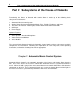
6 Part 2 Subsystems of the Smoke Alarm & House of Hazards Part 2 Subsystems of the House of Hazards Functionally, the House of Hazards with Smoke Alarm is made up of the following basic subsystems and features: 1. 2. 3. 4. 5. Automatic Music Control System Smoke Alarm Character with Moving Mouth, Eyes, Eyelids, Eyebrows, and Arms. The House of Hazards: Room lights, Smoke Alarm LEDs and hazard LEDs CD Player Power Supply Optional Features 6. Control Box 7. Voice System – Headset Microphone 8.
Chapter 3 Smoke Alarm Character 7 Chapter 3 Smoke Alarm Character The Smoke Alarm has moving eyes, eyelids, arms, eyebrows, and a moving mouth. These functions are operated by individual servo motors in the Smoke Alarm itself. The signal comes from the main control board to operate these functions. The signal wire that comes from the main control board goes to a servo board inside the Smoke Alarm. The servo board decodes the pulse train signal into individual signals for each servo motor.
8 Chapter 3 Smoke Alarm Character Care of the Plastic Cover for the Smoke Alarm • • • • • • The cover is made of ABS plastic and needs to be cleaned with mild soap and water with a soft cloth. Windex or water and a soft cloth can be used. Do not use solvents or abrasive cleaners. When transporting the Smoke Alarm on the base, keep it secure so that it does not bounce around. Put a cover or a blanket over it to protect it. Do not put it in the back of an open truck or trailer.
Chapter 4 The House with Lights 9 Chapter 4 The House with Lights The House lighting system is made up of two main light types; the room panel lights and the LED lights. The LED lights are used for the smoke alarms in each room and to indicate the hazards. Each light and each of the hazards have a switch on the control panel. The Smoke Alarm LED lights come on all together with one switch.
10 Chapter 4 The House with Lights Changing a room light bulb: 1. Remove the front panels enough to get to the bulb. 2. Replace the bulb in the socket and make sure the new bulb is screwed in tight. 3. To put the panel back in, flex it and pop it in to the slots. How to change a LED hazard light: The Super Bright light emitting diodes should last for a very long time.
Chapter 5 CD Player Instructions 11 Chapter 5 CD or MP3 Player Operation and Maintenance If you have the CD player: Pushing the CD Play/Pause button on the CD player activates the Compact Disc player. How to Play A CD 1. Make sure that your power and audio wires are plugged in to the CD player. 2. Slide the OPEN button to open the cover. 3. Insert the CD in with the label side up. 4. Press the play/pause button to play. 5.
12 Chapter 5 CD Player Instructions 6. Start the track with the play button. The stop button has a box symbol. Caution: Do not disconnect the audio headphones plug while playing. This will lock up the MP3 player. To reset it just remove the battery from the player and put it back in.
Chapter 6 Power Supply Use 13 Chapter 6 Power Supply The power for the system is supplied by a power supply or a battery. The House comes with a power supply that is rated at 13.8 Volts 10 Amps. There is an optional battery and battery charger you can obtain if you think you will be in locations that will not have 110 Volt outlets available. The battery is a 12 Volt 33AH Gel type battery. Either the power supply or battery connect in to the same connection on the back of the house.
14 Chapter 7 Operator Control Box Part 3 Optional Features Chapter 7 Control Box The control box allows the operator to use the House and Smoke Alarm in manual mode. The operator can turn on the room lights, smoke alarm lights or hazard lights individually to emphasize the dangers in certain rooms and do a walk through of the entire house, room by room. The operator can also operate all of the functionality of the Smoke Alarm and interact with your audience.
Chapter 8 Voice System 15 Chapter 8 Voice System The Voice System allows you to be the voice and hearing of the Smoke Alarm. It includes a headset microphone, audio board in the control box and the audio board on the House is part of the system also. When you talk into the microphone the signal goes first to the audio board in the control box where it is mixed with other audio and then sent to the audio board in the House. The House audio board amplifies the signal to be put on the speakers.
16 Chapter 9 Video Camera and Monitor Chapter 9 Video Camera and Monitor The video camera is typically located in the base unit of the Smoke Alarm. The video signal runs through the wire extension from the base unit to the control box. There are two wires that go from the control box to the monitor. One has a black barrel plug. This is the power wire. The other has a yellow plug. This is the video signal.
Chapter 10 Voice Modifier 17 Chapter 10 Voice Modifier The pitch shifter (voice modifier) can change the operators voice to disguise it and create the Smoke Alarm character voice. The operators voice signal is sent to the audio board in the control box. The audio board sends your voice to the Input of the pitch shifter. It is modified and sent from the shifter Output back to the audio board again and then it mixes with the other audio going to the Speakers. 1. 2. 3. 4. 5. 6. 7. 8. 9.
18 Chapter 10 Voice Modifier The shifter gets power from the control box; no internal battery is needed. If the cover of the control box ever needs to be removed, do not allow the shifter power wire plug, to contact the metal box. The metal box surface has a ground connection. The fuse related to the shifter is the audio fuse located on the fuse block. Below is a typical setting for the Buzz Smoke Alarm voice.
Chapter 11 Battery Option 19 CHAPTER 11 Battery System The battery available for the House is a rechargeable sealed lead-acid Gel type battery 12 Volt 31AH. This type of battery is very dependable and safe. It can be repeatedly charged and discharged. This is an optional item needed only if you are at a location that does not have electrical outlets. Connecting The battery connects to the same connection as the power supply, to the red and black connector on the back of the House.
20 Chapter 11 Battery System: Battery Charger BATTERY CHARGER Instructions for Proper Use and Operation WARNING: HAZARD OF EXPLOSIVE GAS MIXTURE When charging, a lead acid battery gives off hydrogen gas. The Gel type battery is a lead acid battery with pressure relief type vents. Although it only gives off a small percentage of the gas that a wet lead acid battery does, the following precautions should be observed: 1. 2. Do not position your face over the battery, at any time while making connections.
21 If the charger does not stay on after 10 minutes, disconnect the charger from the battery. The battery most likely has a shorted cell and needs replacement. 5. In some cases, a battery, which is discharged completely, will not draw any noticeable current when the charger is connected and the power cord plugged in. A battery that behaves in this way is most likely in a "sulfated" condition. The condition is caused by leaving a battery in a discharged condition for a length of time.
22 Chapter 12 Maintenance: Checklist PART 4 CHAPTER 12 Maintenance Regular Maintenance Checklist Periodically the robot should receive a thorough inspection. 1. Examine the exterior of the House and Smoke Alarm and make repairs as necessary. See the body repair instructions if needed. 2. Remove the House back panel and the Smoke Alarm back cover. Check all bolts and nuts for tightness. 3. Examine electrical wiring and connectors for looseness and wear. 4.
Chapter 12 Maintenance: Recommended Tool Kit Recommended Tool Kit Fuses- 3 and 5 Amp (ATO Type) 4" cable ties Precision regular Phillips screw drivers Screwdrivers (flat head and Phillips) Socket and ratchet set Needle nose pliers Crimper/Wire strippers Wire cutters (diagonal cutters) 7/16" & 3/8" wrenches Set of Allen wrenches (Especially 3/32" and 1/8" sizes) Extra 9 Volt alkaline batteries Small soldering iron and solder Small can all purpose lubricant Digital Multimeter (Volts/Ohms) 23
24 Chapter 12 Maintenance: Painting the Body PAINTING OF THE ABS PLASTIC The following information are only suggestions of painting methods. Contact a professional for assistance. Preparing the surface: The robot body is an ABS plastic and should be cleaned before painting to remove oils and dirt. This is especially true if the surface has had a protectorant such as Armor-All put on it.
Chapter 12 Maintenance: Repair of the Body 25 REPAIR OF THE HOUSE OR SMOKE ALARM PLASTIC Materials Super glue ABS or PVC clear medium bodied glue Fiberglass mesh rubber gloves 1. Hold the crack together tightly so that the glue you put on the inside of the body does not run through the crack on to the outside of the body. This would etch into the plastic. 2.
26 Chapter 12 Maintenance: Storage STORAGE If you put the system in storage for a period of time, you should do the following: 1. Clean the Plastic. Clean the plastic as described in the maintenance section (If robot is stored with a dirty body it may be harder to clean at a later date, as stains may become permanent). 2. Always store it with a cover. Storing the system with a dust cover on it will keep it clean and protect the Smoke Alarm and House from scratches.
27 APPENDIX A ROBOT PARTS IDENTIFICATION
28 Smoke Alarm Inside View Eyebrow Servos Arm Servos Eyelid Servos Eyes L/R Servo Mouth rod Servo Arm Servo Board
29 Smoke Alarm Back View Thumb screws on bottom of feet 9 Volt Battery Compartment for demonstration purposes Remove these three screws only to remove the back cover
30 Smoke Alarm Servo Board Servo Outputs to Servo Motors in the Smoke Alarm Signal and 12V Power Input Output Assignments to Servos 1. Mouth 2. Eyes Left/Right 3. Left Arm 4. Right Arm 5. Left Eyelid 6. Right Eyelid 7. Left Eyebrow 8.
31 Base Unit Electronics Video Cam Connections Main Processor Board Smoke Alarm Signal Bundle Wire feed through slot Fuse Block Alarm Buzzer Audio Board Microphone wire Main On/Off Switch To House Volume To Operator Control Box Power Connector Note: The current base unit also has a PA system connection and volume not shown here.
32 House Back Inside View House Lights and LED Switching Board LED Distribution Board LED Distribution Board 16 pin connector
33 House Lights Switching Board Ribbon Cable to LED Distribution Boards 12 Volt Power
34 Operator Control Box Inside View Audio Board Control Box Main Processor Board
35 Fuse Block Detail Base Unit Fuse Block (ATO Type Fuses) 1 2 3 Fuse Block The Power to the fuse block comes from the main switch. Fuse 1 (3 Amp) Base Unit Power – All base circuit boards and Buzz. Fuse 2 (5 Amp) House Power – Lights and LED circuit boards. Fuse 3 (3 Amp) Control Box Power – Audio and processor board in the control box.
36 Notes
37 Technical Tips