
User's Guide

WR-3700 Series User’s Guide
32
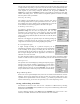
5. Gain sets the pre-processing numerical gain of the signal inside the DSP. This parameter
helps to resolve the ‘signal-to-noise vs. audio distortion’ trade-off. If the filtered signal
sounds too distorted, choose a lower gain. The ‘AGC’ option activates automatic gain
control algorithm. This function does not supplement the main AGC for the receiver, as
it is applied only 'inside' the DSP as an automatic numerical amplification adjustment.
6. Low/High/Centre/Width parameters control the corresponding pass band frequencies of
the filter. The two pairs (Low/High and Centre/Width) are synchronized, so that change
in one parameter is subsequently transformed into change of the others. The entered
numbers are rounded to 10Hz steps.
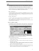
7. Interactive filter tunning control. You can independently drag the lower and upper
transition bands with the mouse. It is also possible to move the whole pass band ('tune'),
simply by dragging the upper horizontal part of the displayed response.
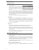
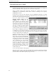
8. Real time FFT display. Shows the spectrum of the audio signal. The vertical range of
the display is 80dB. Frequency axis marks are displayed above the FFT display.
9. FFT Source - selects whether the FFT is computed before or after filtering of the signal.
10. Bar toggles between displaying spectral envelope and spectral lines, while Grid enables
the green rectangular grid on the FFT display.
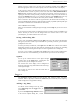
11. Exit stops the Signal Conditioner applet and unloads the DSP, so that other task
(different applet or the Sound Recorder) can be performed. It is possible to stop the
applet by selecting ‘DSP - Stop applet’ in the WR-3700i-DSP menu.
12. About displays the version info.
13. Settings is used to store and quickly retrieve different combinations of control
parameters. To Store current setting, type any desired name into the 'listbox' line and the
click the 'Save' button. To recall pre-stored settings, simply select the proper name in the
'listbox'. To remove selected item form the list box, click the 'Delete' button.
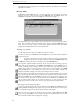
Note: The Band pass filter uses finite impulse response (FIR ) design, so the phase delay
response is inherently linear. This filter is ideal for 'cleaning up' any data mode before
outputting the signal to a third party decoder. To adjust the filter to any FSK modulated
signal, set the lower cutoff frequency ('LOW') slightly below the lower tone and the higher
cutoff frequency above the higher tone of the signal.