
User's Guide

WR-3700 Series User’s Guide
30
External Antenna Control
Many installations use at least one antenna, each antenna being suited for a particular
frequency band. For adequate full spectrum reception, at least two antennas are required: an
HF and a VHF/UHF antenna, typically a wire and a discone respectively.
Using a suitable external logic control box connected to a parallel port on the PC,
WiNRADiO can automatically switch between antennas according to the frequency
WiNRADiO is tuned to.
If this feature is used, the entire frequency range of WiNRADiO (150 kHz to 1.5 GHz)
should be covered. Otherwise, if you tune to an unspecified range, the reception can be very
poor due to the wrong antenna being selected.
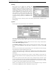
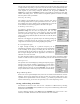
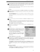
To set the antenna control up, select
External antenna control from the
Configure menu. A dialog box will
appear showing any frequency ranges
that control the antenna, the parallel port
and the data sent to the port. You should
not connect any printers to the parallel
port you are using for antenna control
and similarly, you should not specify a
parallel port that a printer is connected to.
If you require an additional parallel port,
an additional I/O card needs to be installed. You need to make sure it can be set up for LPT2
or 3 and the serial ports (if the card contains any) can be configured or disabled, otherwise
they may conflict with your existing ports.
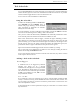
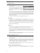
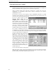
To add a frequency range, click on the
Add button. Another dialog box will
appear where you can enter the frequency
range, select the parallel port and the data
sent to the port. You have three methods
of specifying the data to send: decimal
value, hexadecimal value and selecting
the pins that go high (5 volts). If you
change one setting, all the other settings
change appropriately. A diagram of the
parallel port (showing the socket on the
PC) is shown to assist with wiring up a
custom control unit.
You can also edit and delete existing ranges.
When the receiver enters a range, the associated data is sent to the parallel port and the
strobe line (pin 1, normally low) is pulsed to allow external logic to latch any data it requires
(the data remains until another frequency range is entered).