
User's Manual
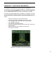
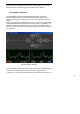

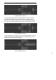
Table Of Contents
- WiNRADiO
- G3 Series Radio Receiver
- Introduction
- Installation
- Getting Started
- Connecting the Antenna
- Using WiNRADiO G3 SERIES
- Appendix A - Troubleshooting
- Appendix B – Sound Card Controls
- Appendix C - Dealing with Interference
- Appendix D - Inside WR-G3 SERIES
- Appendix E – Professional Demodulator
- Appendix F - Developer Support
- Declaration of Conformity

- 50 -
The front panel of the Professional Demodulator looks similar to the
Standard one. Note in particular the added DSB and ISB modes, the
continuous IF filter bandwidth control, enhanced Audio AGC (the time
constants are user definable in the Setup window), and a row of IF
bandwidth preset buttons at the bottom. The numbers on top of the IF
bandwidth preset buttons indicate the associated bandwidth (in kHz). These
presets, too, are entirely user-definable.
To change the IF bandwidth, you can type the desired value (in Hz) directly
in the IF bandwidth editbox, or use the associated up/down buttons.
Do not overlook the small but very significant slider button between the
bandwidth up/down buttons: It allows you to change the IF bandwidth within
a large range, by moving the slider cursor up and down, with a very
impressive effect.
In the spectrum scope, the selected IF bandwidth is shown using a different
background color around the center frequency. The portion of the signal
spectrum falling within the IF bandwidth is shown in yellow.
Adjusting Demodulator Parameters
The entire demodulation process can be observed in the demodulator
structure window, accessible from within the Demodulator Settings (press
the
Settings
button under the
CW
mode button), then the large
View
Demodulator Structure
button). Each mode has its own associated
structure. By selecting the mode either using the front panel or the tabs at
top-right of the Demodulator Settings window, you can observe the different
structures applicable to the selected modes. Each mode also has a number
of filter settings to experiment with.
The meaning of each filter is best understood looking at the demodulator
structure. All of these filters are linear phase
FIR
(
Finite Impulse Response
),
with cut-off frequencies and lengths that can be adjusted and optimized by
the user, either by direct typing in the parameter or using the sliders,
according to the received signal characteristics.
Each filter length (i.e. the number of its
taps
), can be an odd number
between 3 and 255. The more taps, the better the filter characteristics, and
the better the selectivity of the receiver, but the computing task for the CPU
is harder. Therefore, while increasing the filter lengths, always watch the
CPU usage in order not to starve the operating system of CPU resources
(80% is a good upper limit). Starving the system of CPU resources