
User's Manual
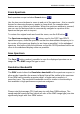
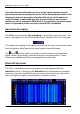
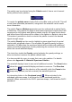
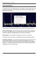
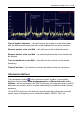
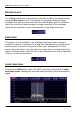
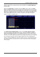
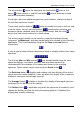
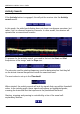
Table Of Contents
- Table of Contents
- Introduction
- The Hardware
- Installation
- Getting Started
- Inside the Excelsior
- Resizing the Application Window
- Drop-Down Menu Controls
- Tuning the Excelsior
- Receiver Selection
- Mode Selection
- Function Tabs
- Spectrum Scopes
- Recording Functions
- Attenuator
- Preamplifier
- S-meter
- Top Menu Bar
- File
- Options
- Auto-mute RX not in focus
- Enable second RX
- Filter Length
- Front Panel LED
- Display Offset
- Time
- Keyboard Shortcuts
- VSC Set-up
- Audio Buffering
- AMS Capture Range
- Audio Output
- Show Measurements
- Show Data Rates
- Of particular interest to many users will be the CPU load (excessive CPU load may cause sluggish behaviour or freezing of the computer), and Audio latency. Apart from DDC bandwidth, CPU load may be minimized by reducing the Demodulator filter length (...
- Note: When measuring sensitivity using SINAD, it is very important that the Audio Filter is enabled and the cut-off frequencies (and for FM measurements, also the de-emphasis) are set according to the specified test conditions. Proper audio filtering ...
- Show Waterfall Timestamps
- Calibration
- Hand-Off Receiver
- Color scheme
- Restore factory defaults
- Memory
- Scheduler
- Scanner
- Logger
- Plugins
- Power Switch
- Date and Time Display
- Appendix A – SDR and DDC Primer
- Appendix B – Troubleshooting
- Appendix C – USB Interface Diagnostics
- Appendix D – Dealing with Interference
- Appendix E – G39DDCi PCIe Card Connections
- Appendix F – Waterfall Spectrum Palettes
- Appendix G – Recording File Formats
- Appendix H – Compliance Declarations
- Appendix I – Safety Disposal

WiNRADiO G39DDC User’s Guide
77
Markers (right click on spectrum) are also available in the Audio Spectrum
display mode.
When the Audio filter is enabled (using the Filter button under the Audio
tab), its passband will be shown as a gray area superimposed over the audio
spectrum. The low and high cut-off frequencies of the filter can be graphically
adjusted by dragging the left and right edges of the displayed passband. The
input audio signal to the filter is shown in a darker color while the filtered
output is shown in a lighter color.
The ASR (Audio Sampling Rate) control of the Audio spectrum scope
alters the sampling rate of the output audio, making it possible to achieve a
wider demodulated bandwidth. The available values are 32, 48, 64, 96 and
128 kHz. The audio spectrum window also changes according to the sampling
rate, showing a spectrum width of approximately half of the sampling rate.
Finally, clicking the RF button while the audio spectrum is displayed will quite
the audio spectrum mode and return to the RF spectrum mode, showing the
DDC2 output.