
User's Manual
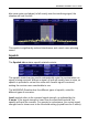
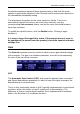
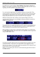
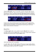
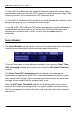
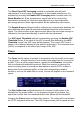
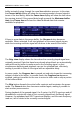
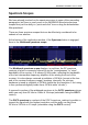
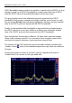
Table Of Contents
- Table of Contents
- Introduction
- The Hardware
- Installation
- Getting Started
- Inside the Excelsior
- Resizing the Application Window
- Drop-Down Menu Controls
- Tuning the Excelsior
- Receiver Selection
- Mode Selection
- Function Tabs
- Spectrum Scopes
- Recording Functions
- Attenuator
- Preamplifier
- S-meter
- Top Menu Bar
- File
- Options
- Auto-mute RX not in focus
- Enable second RX
- Filter Length
- Front Panel LED
- Display Offset
- Time
- Keyboard Shortcuts
- VSC Set-up
- Audio Buffering
- AMS Capture Range
- Audio Output
- Show Measurements
- Show Data Rates
- Of particular interest to many users will be the CPU load (excessive CPU load may cause sluggish behaviour or freezing of the computer), and Audio latency. Apart from DDC bandwidth, CPU load may be minimized by reducing the Demodulator filter length (...
- Note: When measuring sensitivity using SINAD, it is very important that the Audio Filter is enabled and the cut-off frequencies (and for FM measurements, also the de-emphasis) are set according to the specified test conditions. Proper audio filtering ...
- Show Waterfall Timestamps
- Calibration
- Hand-Off Receiver
- Color scheme
- Restore factory defaults
- Memory
- Scheduler
- Scanner
- Logger
- Plugins
- Power Switch
- Date and Time Display
- Appendix A – SDR and DDC Primer
- Appendix B – Troubleshooting
- Appendix C – USB Interface Diagnostics
- Appendix D – Dealing with Interference
- Appendix E – G39DDCi PCIe Card Connections
- Appendix F – Waterfall Spectrum Palettes
- Appendix G – Recording File Formats
- Appendix H – Compliance Declarations
- Appendix I – Safety Disposal

WiNRADiO G39DDC User’s Guide
70
DDC2 bandwidth always needs to be smaller or equal to that of DDC1, so if an
attempt is made to set DDC1 bandwidth to a lower value than that of DDC2,
then the DDC2 value will automatically adjust to that lower value.
The grey shaded area in the wideband spectrum represents the DDC1
bandwidth. Both receiver channels are visible, with the one in focus (i.e. with
the associated RX tab selected) being highlighted. Similarly, the grey shaded
area in the DDC1 spectrum represents the DDC2 bandwidth.
Finally, the demodulator filter bandwidth is represented by a shaded area in
the DDC2 spectrum, and is also visible as a darker area inside the shaded
area of the DDC1 spectrum that represents the DDC2 bandwidth.
Even though their functionality is different, all these three spectrum scopes
utilize some common controls. Let us examine these common controls first,
and leave the specific features of each spectrum scope till last.
The controls of the DDC spectrum scopes are made visible by pressing the
“toolbox” button
, while in the wideband spectrum scope these are visible at
all times.
Pressing the button in either of the DDC spectrum displays will reveal a
“toolbox worth” of controls on the right-hand side: