
User's Manual
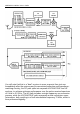
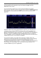
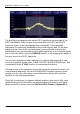
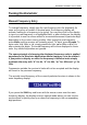
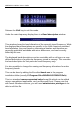
Table Of Contents
- Table of Contents
- Introduction
- The Hardware
- Installation
- Getting Started
- Inside the Excelsior
- Resizing the Application Window
- Drop-Down Menu Controls
- Tuning the Excelsior
- Receiver Selection
- Mode Selection
- Function Tabs
- Spectrum Scopes
- Recording Functions
- Attenuator
- Preamplifier
- S-meter
- Top Menu Bar
- File
- Options
- Auto-mute RX not in focus
- Enable second RX
- Filter Length
- Front Panel LED
- Display Offset
- Time
- Keyboard Shortcuts
- VSC Set-up
- Audio Buffering
- AMS Capture Range
- Audio Output
- Show Measurements
- Show Data Rates
- Of particular interest to many users will be the CPU load (excessive CPU load may cause sluggish behaviour or freezing of the computer), and Audio latency. Apart from DDC bandwidth, CPU load may be minimized by reducing the Demodulator filter length (...
- Note: When measuring sensitivity using SINAD, it is very important that the Audio Filter is enabled and the cut-off frequencies (and for FM measurements, also the de-emphasis) are set according to the specified test conditions. Proper audio filtering ...
- Show Waterfall Timestamps
- Calibration
- Hand-Off Receiver
- Color scheme
- Restore factory defaults
- Memory
- Scheduler
- Scanner
- Logger
- Plugins
- Power Switch
- Date and Time Display
- Appendix A – SDR and DDC Primer
- Appendix B – Troubleshooting
- Appendix C – USB Interface Diagnostics
- Appendix D – Dealing with Interference
- Appendix E – G39DDCi PCIe Card Connections
- Appendix F – Waterfall Spectrum Palettes
- Appendix G – Recording File Formats
- Appendix H – Compliance Declarations
- Appendix I – Safety Disposal

WiNRADiO G39DDC User’s Guide
25
not be possible as the computer may then become sluggish and the
application may “freeze”.
The chunk of the IF spectrum as seen and processed by the primary
downconverter (DDC1) is shown at top-left; this is called the DDC1 spectrum.
Its bandwidth is determined by the DDC1 control at the top of the DDC1
spectrum:
Anywhere within the primary downconverter spectrum, you can place the
secondary downconverter (DDC2) to further refine and narrow-down the
portion of spectrum you wish to work with. The maximum DDC2 bandwidth is
320 kHz. The DDC1 bandwidth must be always greater than (or equal to)
DDC2 bandwidth, and the bandwidths will adjust themselves automatically to
comply with this rule, if one of them is changed.
The spectrum display at top right of the application window shows the
spectrum as seen and acted upon by the secondary downconverter (DDC2).
This spectrum represents the output of the final decimation process
(performed inside the actual receiver, i.e. inside its FPGA) and is available for
final filtering and demodulation that is performed entirely outside of the
receiver hardware, by the PC application.